
On this page
Alternating Current is Chapter 7 of the NCERT Class 12 Physics textbook, Part I (reprint 2026-27). The CBSE Physics syllabus for 2026-27 covers peak and rms values, reactance, impedance, the LCR series circuit (phasors only), resonance, power factor, wattless current, the ac generator and the transformer. The terms below follow NCERT's usage. For answer-writing and a revision plan, see our Alternating Current Class 12 board exam guide.
What do peak and rms values mean?
Alternating voltage: a voltage that changes like a sine function of time, v = vm sin ωt. Example: the mains supply in your home.
Alternating current: the current such a voltage drives, reversing direction every half cycle.
Peak value (amplitude): the largest value reached in a cycle, written vm or im.
Angular frequency (ω): how fast the oscillation repeats, ω = 2πν, where ν is the frequency in hertz.
Average current over a cycle: zero for a sinusoidal current, because the positive and negative halves cancel.
rms (effective) value: the steady dc value that would give the same average heating, I = im/√2 ≈ 0.707 im, and V = vm/√2. Example: NCERT shows that a 220 V household supply is an rms value with a peak of about 311 V. Don't confuse with: the average value, which is zero over a full cycle.
How do phasors show R, L and C in an ac circuit?
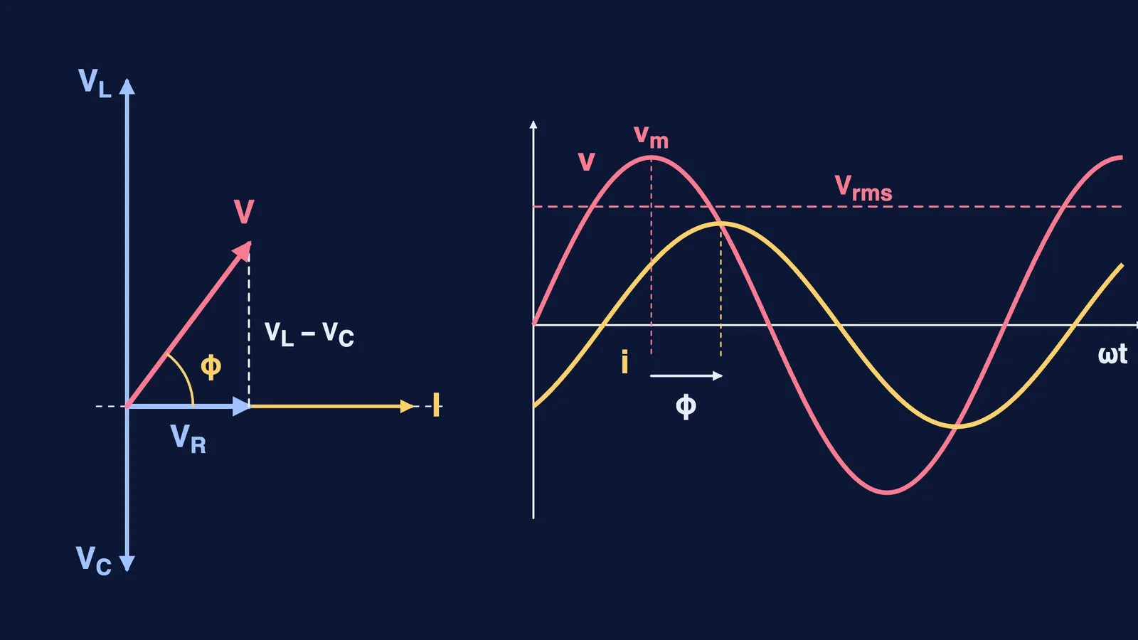
Phasor: an arrow spinning at angular speed ω; its length is the peak value and its vertical shadow is the value at that instant. Voltage and current remain scalars.
Phase difference (φ): how far one quantity is ahead of or behind another in its cycle. "Leads" means it peaks earlier; "lags" means later.
Purely resistive circuit: current and voltage are in phase, and v = iR holds at every instant, as with dc.
Purely inductive circuit: the current lags the voltage by π/2 (a quarter cycle).
Inductive reactance (XL): the inductor's opposition to ac, XL = ωL, in ohms. It grows with frequency. Example: NCERT Example 7.2 finds 7.85 Ω for a 25.0 mH inductor at 50 Hz.
Purely capacitive circuit: the current leads the voltage by π/2.
Capacitive reactance (XC): the capacitor's opposition to ac, XC = 1/ωC, in ohms. It falls as frequency rises. Example: a lamp in series with a capacitor glows on ac but not on dc. Don't confuse with: XL, which rises with frequency.
What happens in a series LCR circuit?
Series LCR circuit: R, L and C in one loop with an ac source; the same current flows through all three at every instant.
Impedance (Z): the total opposition to current, Z = √(R² + (XC − XL)²), in ohms. Don't confuse with: resistance, which is only one side of it.
Impedance diagram: a right triangle with sides R and (XC − XL) and hypotenuse Z.
Phase angle: tan φ = (XC − XL)/R. If XL > XC the circuit is mainly inductive and the current lags; if XC > XL it is mainly capacitive and the current leads. Example: NCERT Example 7.8 has R = 3 Ω, XL = 8 Ω and XC = 4 Ω, so Z = 5 Ω and the current lags by 53.1°, the case drawn above.
Resonance: the condition XL = XC, where Z falls to its minimum, R, and the current amplitude is largest.
Resonant frequency (ω0): ω0 = 1/√(LC). Example: tuning a radio means changing C until ω0 matches the station's frequency.
No resonance in RL or RC circuits: both L and C are needed, so their voltages can cancel.
What are power factor and wattless current?
Average power: P = VI cos φ, using rms values. Power is dissipated only in the resistance.
Power factor: cos φ, equal to R/Z in a series circuit; it is 1 for a pure resistor and at resonance.
Wattless current: current in a circuit with only L or only C; cos φ = 0, so no net power is drawn although current flows.
Wattless and power components: Iq, at right angles to the voltage, carries no power; Ip, in phase with it, does.
Power factor improvement: adding a capacitor in parallel so its leading current cancels the lagging wattless current. A low power factor needs more current for the same power, so more I²R loss in transmission.
How do transformers and ac generators work?
Transformer: raises or lowers an ac voltage by mutual induction, using insulated primary (Np turns) and secondary (Ns turns) coils on a soft-iron core.
Ideal transformer: no losses and all flux links both coils, so Vs/Vp = Ns/Np and Is/Ip = Np/Ns.
Step-up transformer: Ns > Np, so voltage rises and current falls. Example: in NCERT, 100 and 200 turns turn 220 V at 10 A into 440 V at 5.0 A. Don't confuse with: a step-down transformer, where Ns < Np.
Energy losses: flux leakage, resistance of the windings (I²R heating), eddy currents (reduced with a laminated core) and hysteresis in the core.
AC generator: a coil (the armature) turned in a uniform magnetic field, so the flux through it keeps changing and an emf ε = NBAω sin ωt is induced; it turns mechanical energy into electrical energy. Slip rings and brushes connect it to the circuit. NCERT explains it in Section 6.8 of Chapter 6, though the syllabus lists it under this chapter.
LC oscillations are not in the current NCERT chapter, so they are left out.
How to learn these terms
Learn the three phase rules as one line: R in phase, L current lags, C current leads by π/2.
Drill the pairs: XL vs XC, rms vs peak, impedance vs resistance, step-up vs step-down.
Redraw the phasor diagram above from memory, then build the impedance triangle from it.
Revise mutual induction in our electromagnetic induction Class 12 guide before the transformer terms.
For harder numericals, try our Alternating Current for JEE Main guide.
If phasors feel abstract, the Fermi Simulation Lab has interactive simulations for the ideas that are easier to see than to read.