
On this page
This sheet covers Chapter 7 of the NCERT Class 12 Physics Part I textbook (Reprint 2026-27), in the chapter's order. Every formula was checked with SymPy.
The CBSE Physics curriculum for 2026-27 lists peak and rms values, reactance, impedance, the LCR series circuit (phasors only), resonance, power factor, wattless current, the AC generator and the transformer. The generator formula is in Section 6.8 of the NCERT Electromagnetic Induction chapter. LC oscillations and sharpness of resonance (quality factor) have no section in the 2026-27 chapter, so they are left out.
For answer layouts and a revision plan, see our Alternating Current Class 12 board exam guide. For proofs, see our Alternating Current Class 12 derivations.
What are peak and rms values of AC?
Symbols: v, i instantaneous voltage (V) and current (A); vₘ, iₘ peak values; ω angular frequency (rad/s); ν frequency (Hz); V, I rms values; R resistance (Ω); P average power (W).
v = vₘ sin ωt, with ω = 2πν.
Pure resistor: i = iₘ sin ωt, iₘ = vₘ/R. Current and voltage are in phase.
rms current: I = iₘ/√2 ≈ 0.707 iₘ. rms voltage: V = vₘ/√2 ≈ 0.707 vₘ.
V = IR, and average power P = I²R = V²/R = VI (resistor only).
Worked example: a 1500 W, 230 V (rms) kettle has R = V²/P = 35.27 Ω and I = P/V = 6.52 A, so iₘ = 9.22 A and vₘ = √2 × 230 = 325.3 V.
Watch for: ratings and meter readings are rms values.
How do reactances of L and C work?
Symbols: L inductance (H), C capacitance (F), X_L and X_C reactances (Ω).
Pure inductor: i = iₘ sin(ωt − π/2), iₘ = vₘ/X_L, X_L = ωL = 2πνL. Current lags voltage by π/2.
Pure capacitor: i = iₘ sin(ωt + π/2), iₘ = vₘ/X_C, X_C = 1/(ωC) = 1/(2πνC). Current leads voltage by π/2.
Average power over a cycle is zero for pure L or pure C.
Worked example: on 230 V, 50 Hz, a 0.20 H inductor has X_L = 2π × 50 × 0.20 = 62.83 Ω (I = 3.66 A); a 100 μF capacitor has X_C = 1/(2π × 50 × 10⁻⁴) = 31.83 Ω (I = 7.23 A).
Watch for: use ω = 2πν, not ν, and convert μF and mH to F and H before substituting.
Series LCR circuit and resonance: which formulas?
Symbols: Z impedance (Ω); φ phase of the current relative to the source voltage (rad or degrees); V_R, V_L, V_C rms voltages (V) across R, L, C; ω₀ resonant angular frequency (rad/s); ν₀ resonant frequency (Hz).
i = iₘ sin(ωt + φ), iₘ = vₘ/Z, I = V/Z, with Z = √(R² + (X_C − X_L)²).
Phase: tan φ = (X_C − X_L)/R. If X_C > X_L the current leads (capacitive); if X_C < X_L it lags (inductive).
Element voltages: V_R = IR, V_L = IX_L, V_C = IX_C, and by phasor addition V² = V_R² + (V_C − V_L)².
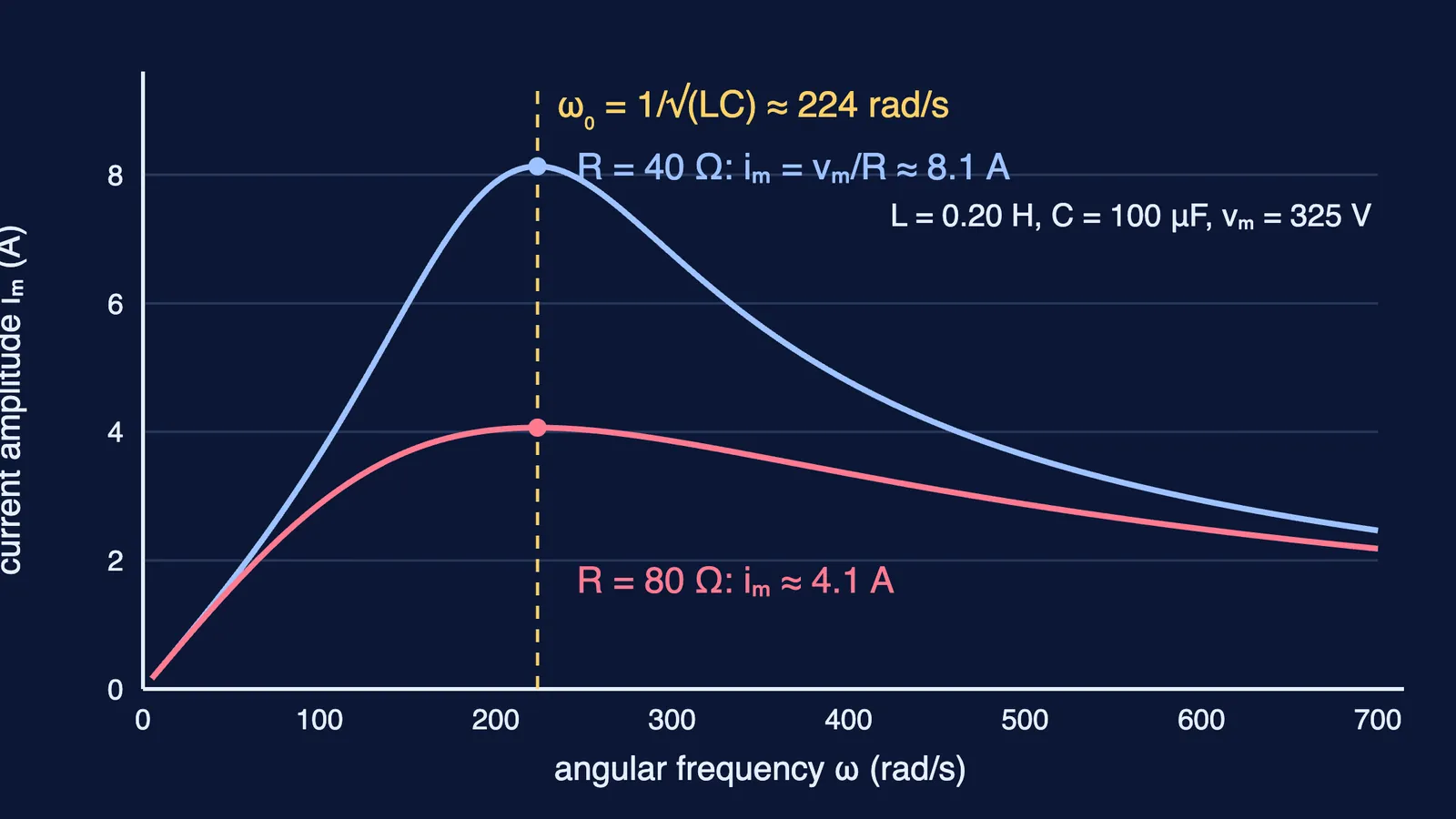
Resonance (needs both L and C): X_L = X_C, so ω₀ = 1/√(LC) and ν₀ = 1/(2π√(LC)). Then Z = R, φ = 0, and iₘ = vₘ/R is the largest current.
Worked example: R = 40 Ω, L = 0.20 H, C = 100 μF on 230 V, 50 Hz. X_C − X_L = 31.83 − 62.83 = −31.0 Ω, so Z = √(40² + 31.0²) = 50.6 Ω and I = 4.54 A. tan φ = −31.0/40 gives φ = −37.8°: the current lags. V_R = 181.8 V, V_L = 285.6 V, V_C = 144.7 V, and √(181.8² + (144.7 − 285.6)²) = 230 V. Resonance is at ω₀ = 1/√(0.20 × 10⁻⁴) = 223.6 rad/s, or ν₀ = 35.6 Hz, where I = 230/40 = 5.75 A.
Watch for: ω₀ = 1/√(LC) is in rad/s. Divide by 2π for ν₀ in hertz.
If phasors feel abstract, the Fermi Simulation Lab has interactive simulations for ideas easier to see than to read.
Power in AC circuits: what is the power factor?
Symbols: P average power (W); V, I rms voltage (V) and current (A); cos φ power factor (no unit).
P = VI cos φ = (vₘiₘ/2) cos φ = I²Z cos φ.
Power factor cos φ = R/Z (series LCR), so P = I²R: only the resistor dissipates power.
Pure R: cos φ = 1. Pure L or C: cos φ = 0, P = 0, and the current is wattless.
At resonance, cos φ = 1 and P = V²/R (W), the largest power this circuit draws as the frequency is varied.
Worked example: for the circuit above, cos φ = 40/50.6 = 0.790 and P = 230 × 4.545 × 0.790 ≈ 826 W (equal to I²R). At resonance P = 230²/40 = 1322.5 W.
Watch for: with peak values P = (vₘiₘ/2) cos φ; dropping the 1/2 doubles the answer.
What are the AC generator and transformer formulas?
Symbols: N turns; B magnetic field (T); A coil area (m²); ε instantaneous emf (V); ε₀ peak emf (V); subscripts p and s for primary and secondary turns, rms voltages (V) and rms currents (A).
AC generator (coil rotating at constant ω in a uniform B, perpendicular to B at t = 0): ε = NBAω sin ωt, so ε₀ = NBAω = NBA(2πν).
Ideal transformer (no flux leakage, negligible winding resistance): V_s/V_p = N_s/N_p.
No losses: I_pV_p = I_sV_s, so I_s/I_p = N_p/N_s.
N_s > N_p steps voltage up. Real losses: flux leakage, winding resistance, eddy currents, hysteresis.
Worked example: a 100-turn, 0.050 m² coil at 50 rev/s in 0.40 T gives ε₀ = 100 × 0.40 × 0.050 × 2π × 50 = 628.3 V. A transformer taking 230 V to 11.5 V with N_p = 2000 needs N_s = 100; for I_s = 2.0 A, I_p = 0.10 A.
How to revise this formula sheet
Draw the R, L and C phase pictures from memory; the sign of φ follows from them.
Rework the LCR example with C = 20 μF and check that X_C − X_L changes sign and φ flips.
Practise mixed numericals with our Alternating Current JEE Main practice questions with solutions.