
On this page
Chapter 7 of the NCERT Class 12 Physics Part 1 textbook (Reprint 2026-27) starts most results from one move: apply Kirchhoff's loop rule to a source v = vm sin ωt. The CBSE 2026-27 Physics syllabus keeps the chapter with the LCR series circuit treated by phasors only, so these are the six derivations the chapter works through, each with setup, steps, result and a common slip. For the revision plan, see our Alternating Current Class 12 guide to board answers and revision.
RMS value: why is I = im/√2?
Setup: a resistor R across v = vm sin ωt (NCERT Fig. 7.1).
The loop rule gives vm sin ωt = iR, so i = im sin ωt with im = vm/R. Current and voltage are in phase.
Instantaneous power is p = i²R = im²R sin²ωt.
Since sin²ωt = ½(1 − cos 2ωt) and cos 2ωt averages to zero over a cycle, ⟨sin²ωt⟩ = ½.
Average power is P = ½ im²R.
The rms current I is the steady current with the same average power: I²R = ½ im²R.
Result: I = im/√2 ≈ 0.707 im, and in the same way V = vm/√2.
Where students slip: arguing that zero average current means zero average power. Power depends on i², which is never negative.
Pure inductor: why does current lag by π/2 and XL = ωL?
Setup: an ideal inductor L (no winding resistance) across v = vm sin ωt (Fig. 7.5).
The loop rule with the self-induced emf: v − L di/dt = 0, so di/dt = (vm/L) sin ωt.
Integrate: i = −(vm/ωL) cos ωt + constant.
The source is symmetric about zero, so the current has no steady part: the constant is zero.
Rewrite −cos ωt as sin(ωt − π/2): i = im sin(ωt − π/2), with im = vm/ωL.
Average power: p = vi = −½ im vm sin 2ωt, which averages to zero over a cycle.
Result: inductive reactance XL = ωL, current lags voltage by π/2, and average power is zero.
Where students slip: keeping the integration constant, or losing the minus sign so the current seems to lead.
Pure capacitor: why does current lead by π/2 and XC = 1/ωC?
Setup: a capacitor C alone across v = vm sin ωt (Fig. 7.7).
The loop rule sets the capacitor voltage q/C equal to the source: q = C vm sin ωt.
Current is the rate of change of charge: i = dq/dt = ωC vm cos ωt.
Rewrite cos ωt as sin(ωt + π/2): i = im sin(ωt + π/2), with im = vm/(1/ωC).
Average power: p = vi = ½ im vm sin 2ωt, which again averages to zero.
Result: capacitive reactance XC = 1/ωC, current leads voltage by π/2, and average power is zero.
Where students slip: saying XC grows with frequency. Doubling the frequency halves it.
Series LCR circuit: Z = √(R² + (XC − XL)²)
Setup: R, L and C in series with v = vm sin ωt; one current i = im sin(ωt + φ) flows through all three (Fig. 7.10).
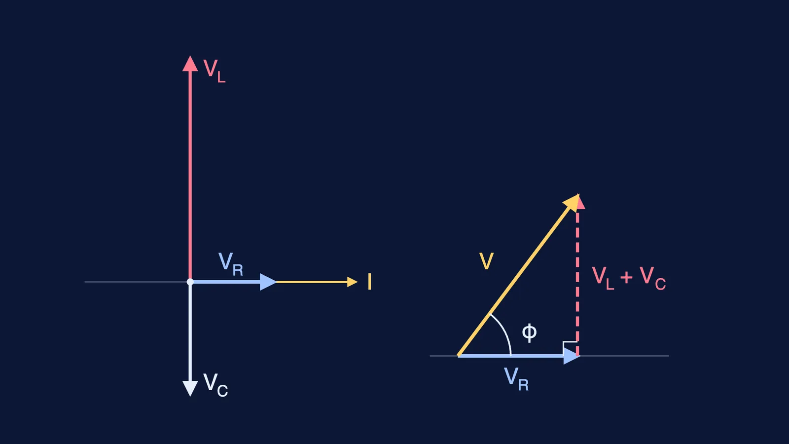
Draw the current phasor I. VR is along I, VL is π/2 ahead of I, VC is π/2 behind I.
Their lengths are vRm = im R, vLm = im XL and vCm = im XC.
VL and VC point in opposite directions, so they combine into one phasor of length |vCm − vLm|.
V is the hypotenuse of the right triangle formed by VR and that phasor: vm² = vRm² + (vCm − vLm)².
Substitute: vm² = im²[R² + (XC − XL)²], so im = vm/Z.
From the same triangle, tan φ = (vCm − vLm)/vRm = (XC − XL)/R.
Resonance: Z is smallest, equal to R, when XC = XL, that is 1/ω0C = ω0L.
Result: Z = √(R² + (XC − XL)²), tan φ = (XC − XL)/R, and resonance at ω0 = 1/√(LC).
Where students slip: adding vR, vL and vC as plain numbers. They are out of phase, so they add only as phasors. An RL or RC circuit cannot resonate.
Power factor: why is P = VI cos φ?
Setup: the series LCR circuit above, with v = vm sin ωt and i = im sin(ωt + φ).
Instantaneous power: p = vi = vm im sin ωt sin(ωt + φ).
Use the product-to-sum identity: p = ½ vm im [cos φ − cos(2ωt + φ)].
Only the second term depends on time, and it averages to zero over a cycle.
So P = ½ vm im cos φ = (vm/√2)(im/√2) cos φ.
Result: P = VI cos φ = I²Z cos φ, where cos φ is the power factor.
Where students slip: using peak values without the factor ½. For a pure L or C, cos φ = 0, so the current is wattless.
Transformer: Vs/Vp = Ns/Np and Is/Ip = Np/Ns
Setup: an ideal transformer: small primary resistance and current, the same flux φ through each turn of both coils, small secondary current (Fig. 7.16).
Secondary (Ns turns): εs = −Ns dφ/dt, and with little current drawn, vs = εs.
Primary (Np turns): back emf εp = −Np dφ/dt, and with zero resistance vp = εp.
Divide: vs/vp = Ns/Np.
With no energy loss, power in equals power out: ip vp = is vs.
Combine: ip/is = vs/vp = Ns/Np.
Result: Vs = (Ns/Np) Vp and Is = (Np/Ns) Ip, so stepping voltage up steps current down.
Where students slip: dropping the three assumptions; real transformers lose energy, as our post on energy losses in a transformer and how each one is reduced explains.
How should you practise these derivations?
Write each one from a blank page, then compare step by step and mark where you first went off.
Draw the phasors before any algebra for the inductor, capacitor and LCR derivations.
Test results on NCERT's numbers: Example 7.8 gives Z = 5 Ω; Example 7.4 gives XC = 212 Ω.
Use them inside questions with our alternating current case study questions with answers.
If lead and lag still feel abstract, the Fermi Simulation Lab has interactive simulations for ideas that are easier to see than to read.