
On this page
Charge a capacitor, connect it to an empty one, and the charge spreads out until both sit at the same voltage. Add up the stored energy afterwards and some of it is missing. Physicists call this the two-capacitor paradox, and it turns up in JEE-style questions because it tests two ideas at once: what is conserved, and what isn't.
How much energy is lost when two capacitors are connected?
You need two rules. First, charge is conserved: the plates joined by the wire are isolated, so their total charge cannot change. Second, a capacitor stores energy U = Q²/2C = CV²/2, held in the electric field between its plates, as the OpenStax University Physics textbook sets out.
Worked example: take C1 = 4 µF charged to 100 V and an uncharged C2 = 2 µF.
Charge before: Q = C1V = 4 µF × 100 V = 400 µC.
Energy before: ½ × 4 µF × (100 V)² = 20 mJ.
After connecting, the capacitors are in parallel, so the common voltage is Q/(C1 + C2) = 400 µC / 6 µF ≈ 66.7 V.
Energy after: Q²/2(C1 + C2) = (400 µC)² / (2 × 6 µF) ≈ 13.3 mJ.
Energy lost: 20 − 13.3 ≈ 6.7 mJ, exactly one third of what you started with.
With letters instead of numbers, the loss is ΔU = C1C2V²/2(C1 + C2), and the fraction lost is C2/(C1 + C2). For two identical capacitors that fraction is one half, which is the classic version of the puzzle described in the two capacitor paradox entry on Wikipedia.
Where does the missing energy go?
Real wires have resistance, and the current that flows while the charge redistributes heats them. The Wikipedia summary of the paradox notes that half the initial energy is dissipated as heat in the wire resistance for two identical capacitors, whatever the size of that resistance (Two capacitor paradox).
What if the wire had zero resistance? In 1979 R. A. Powell of Stanford argued that once the circuit's self-inductance is included, the usual series RC model looks inappropriate for practical circuit values (American Journal of Physics, 1979). In 2002 Timothy Boykin, Dennis Hite and Nagendra Singh showed that in an ideal zero-resistance circuit, radiation fully accounts for the missing energy (American Journal of Physics, 2002). Without resistance the charge oscillates between the capacitors, and the circuit acts as an antenna, as the Wikipedia entry describes.
The paradox comes from leaving the wire out of the diagram. Put it back and energy is conserved: it leaves as heat, radiation, or both.
Why doesn't a thicker wire save the energy?
You can see why by simulating the circuit. Seen from the charge flowing round the loop, the two capacitors act in series, with C = C1C2/(C1 + C2) = 4/3 µF, starting from a 100 V difference.
Set R = 1 kΩ. The time constant is τ = RC ≈ 1.33 ms. The current starts at 100 V / 1 kΩ = 0.1 A and falls as e^(−t/τ).
Track the stored energy, the heat in the resistor (I²R summed over small time steps) and their total.
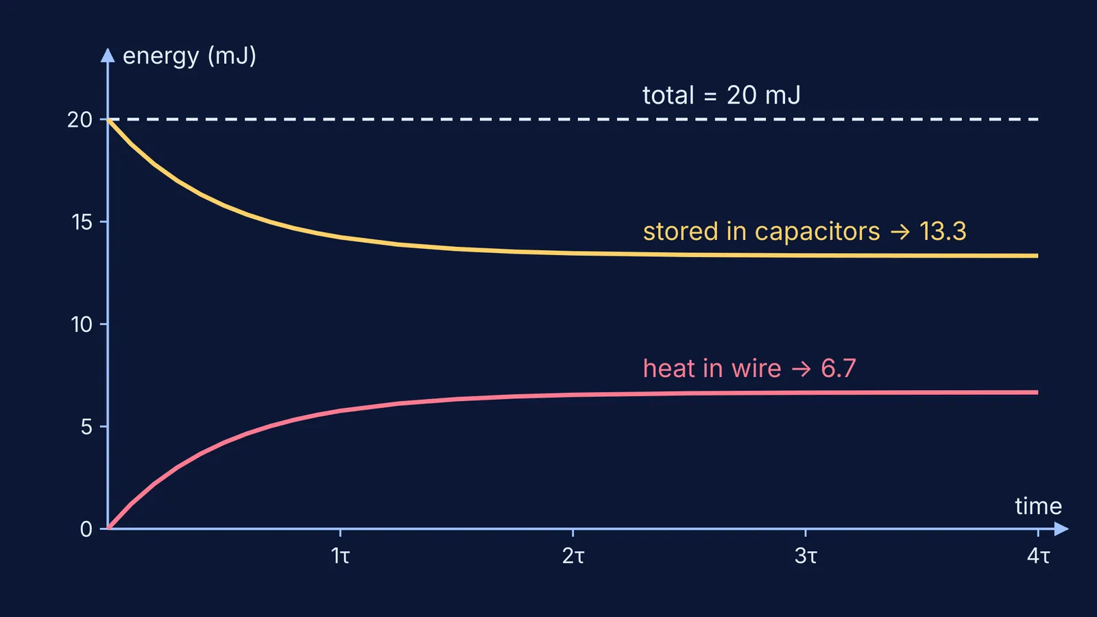
The stored energy falls from 20 mJ to 13.3 mJ, the heat climbs from 0 to 6.7 mJ, and the total stays flat at 20 mJ.
Now set R = 10 Ω. The current starts 100 times larger, at 10 A, but τ shrinks to about 13 µs. Adding up I²R again gives the same 6.7 mJ.
The algebra explains why. The heat is the integral of I²R over time, with I = (V/R)e^(−t/τ), and it comes to ½CV² for the series C. R cancels: a smaller resistance means a bigger current for a shorter time, and the two balance exactly. That is the plot at the top of this page.
If this is easier to see than to read, the Fermi Simulation Lab has interactive simulations for ideas like this one.
How do you handle this in an exam question?
Use this checklist on any problem where capacitors are joined after charging:
Mark which plates are isolated and write the charge balance for them.
Find the common voltage from total charge divided by total capacitance.
Calculate energy before and after with U = Q²/2C, and call the difference heat.
Check that the fraction lost is C2/(C1 + C2) when one capacitor starts empty.
Watch the signs if the capacitors are joined with opposite plates together: the charges partly cancel and more energy is lost.
That last case is worked through in capacitors joined with opposite polarity. For more energy bookkeeping, see a metal slab inserted in a capacitor, and if your loop equations keep flipping sign, read fixing sign errors in Kirchhoff's loop rule.
Stuck on a variation? The Fermi Problem Library has a step-by-step solver that explains the reasoning rather than printing an answer.