
On this page
Every radio link starts with one question: how much of the transmitted power will actually arrive? A compact answer came from Harald T. Friis, a Danish-born engineer at Bell Telephone Laboratories, in a three-page note in the May 1946 Proceedings of the IRE.
Who was Harald Friis?
Friis was born on 22 February 1893 in Næstved, Denmark, and earned his electrical engineering degree in Copenhagen in 1916, according to his Wikipedia biography. He studied radio engineering at Columbia University from 1919 and joined Western Electric's research group in 1920, which became Bell Labs in 1925.
In 1938 he became director of a research team at the Holmdel laboratory of Bell Labs in New Jersey, says the Engineering and Technology History Wiki. In the early 1930s he helped design the receiving system his colleague Karl Jansky used to detect radio noise from our galaxy. With Alfred C. Beck he designed a horn-reflector antenna that became widely used. He and his colleagues urged engineers to measure signal-to-noise ratio, not field strength alone.
He held 31 US patents, received the IRE Medal of Honor in 1955 and died in Palo Alto in 1976, aged 83 (Wikipedia; ETHW).
What does the Friis transmission equation say?
Friis wrote his formula using the effective areas of the two antennas: Pr/Pt = ArAt/(d²λ²), where Pr and Pt are received and transmitted power, Ar and At are the antennas' effective areas, d is the distance and λ is the wavelength (Friis transmission equation).
Textbooks today usually write the same idea with antenna gains: Pr/Pt = GtGr(λ/4πd)² (same source). The two forms agree because an antenna's effective area is A = Gλ²/4π.
Read it as a story in three parts:
The transmitter's power spreads over a growing sphere, so it thins out as 1/d².
A directional transmitting antenna (gain Gt) sends more of that power one way.
The receiving antenna catches a patch of it, in proportion to its effective area.
The 1/d² part is the inverse square law you already meet with light; our inverse square simulation for light shows what doubling the distance does. The λ² term has a subtlety, explained in the free-space path loss article.
Why did Friis write it in 1946?
The paper disclosed a radar transmission formula that had proven useful to the Holmdel group, according to the Engineering and Technology History Wiki. Friis said its advantage over other formulations was that it had no numerical coefficients to remember. The price was describing the transmitting antenna by power flow per unit area instead of field strength, and the receiving antenna by its effective area rather than its power gain or radiation resistance (Friis transmission equation).
How do you calculate received power with the Friis equation?
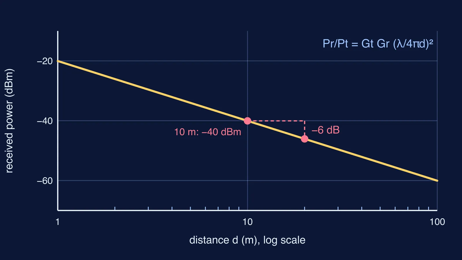
Take a Wi-Fi link at 2.4 GHz: two simple antennas treated as isotropic (gain 1, or 0 dBi), 10 m apart, and a 100 mW transmitter, using the Friis equation and the path-loss shortcut.
Wavelength: λ = c/f = (3 × 10⁸ m/s)/(2.4 × 10⁹ Hz) = 0.125 m.
Spreading factor: λ/(4πd) = 0.125/(4π × 10) ≈ 9.95 × 10⁻⁴.
Square it: about 9.9 × 10⁻⁷. In decibels, 20 log₁₀(9.95 × 10⁻⁴) ≈ −60 dB.
Power: 100 mW is 20 dBm, so Pr ≈ 20 − 60 = −40 dBm, which is 10⁻⁷ W, or 0.1 microwatt.
Check with the shortcut 20 log₁₀(d) + 20 log₁₀(f) − 147.55 in SI units: 20 + 187.6 − 147.55 ≈ 60 dB. Same answer.
Now move the receiver to 20 m. The distance doubles, so the received power falls to a quarter, a drop of 6 dB, to about −46 dBm. Swap in a receiving antenna with 6 dBi of gain and you win that 6 dB back. That trade between distance and antenna gain is one reason directional designs such as the Yagi-Uda antenna are useful.
If converting between decibels and watts trips you up, the Fermi Problem Library has worked problems with a step-by-step solver that explains the reasoning rather than printing an answer.
When does the Friis equation not apply?
The formula rests on ideal conditions, listed on the Friis transmission equation page:
each antenna is in the far field of the other, with d much larger than λ
the antennas are correctly aligned and their polarisations match
the path is unobstructed free space, with no reflections arriving by other routes (multipath)
the signal's bandwidth is narrow enough to use one wavelength
Indoors, walls and reflections break these assumptions, so treat Friis as a starting estimate. A clear line of sight with nothing nearby to reflect from comes closer, as with early satellite links like John Pierce's Echo and Telstar.
If picturing waves spreading over a sphere is the hard part, the Fermi Simulation Lab has interactive simulations for ideas that are easier to see than to read.
When your Wi-Fi bars drop, try the five steps above with your own distance.