On this page
Who invented the Yagi-Uda antenna?
On rooftops across India, fishbone-shaped metallic antennas once pointed toward television broadcast masts. This device is the Yagi-Uda antenna, invented in 1926 by Shintaro Uda and Hidetsugu Yagi at Tohoku Imperial University in Sendai, Japan. In February 1926, they published their findings in the *Proceedings of the Imperial Academy* in "Projector of the Sharpest Beam of Electric Waves" (Yagi and Uda, 1926).
Before their work, producing a directional radio beam required massive curved reflectors or complex transmitter arrays. Uda and Yagi demonstrated that unpowered metal rods placed parallel to a single driven antenna could focus radio waves into a narrow beam. In June 1995, the Institute of Electrical and Electronics Engineers recognized this milestone with an IEEE Milestone plaque at Tohoku University.
Why was it called the Yagi antenna instead of Uda?
Although commonly called the "Yagi antenna," Shintaro Uda (1896–1976) conducted the experimental work. Between 1926 and 1929, Uda published eleven papers in the *Journal of the Institute of Electrical Engineers of Japan*, documenting how element lengths and spacings shaped the radiated beam. His professor, Hidetsugu Yagi (1886–1976), recognized the global significance and published an English survey in June 1928 in the *Proceedings of the Institute of Radio Engineers* citing Uda's papers (Yagi, 1928).
Yagi also secured international patents, filing U.S. Patent 1,860,123 in September 1926 (granted in May 1932) under his name alone. Western engineers learned of the array primarily through Yagi's English paper and patent, popularizing his surname. During this era, radio pioneers were transforming wireless engineering worldwide, including Edwin Armstrong and FM radio.
How does a Yagi-Uda antenna direct radio waves without power?
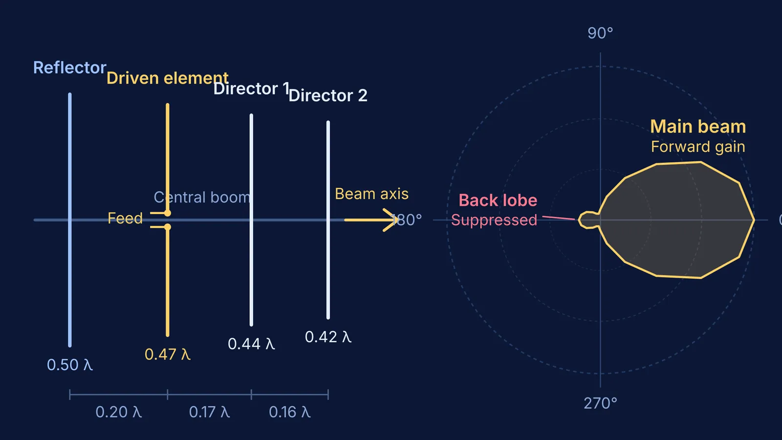
The antenna operates through mutual electromagnetic induction. Only one rod—the driven element—is connected to the transmission line. The remaining rods are parasitic elements receiving no direct electrical feed. As detailed by Yagi and Uda (1926), the driven element induces currents in adjacent rods, which re-radiate waves that interfere with each other:
Reflector (inductive): Placed behind the driven element, the reflector is cut roughly 5% longer than a half-wavelength. Its inductive reactance causes the induced current to lag the incident wave, cancelling rear radiation and reinforcing it forward.
Directors (capacitive): Placed in front of the driven element, directors are cut roughly 5% shorter than a half-wavelength. Their capacitive reactance causes the induced current to lead the incident wave, pulling electromagnetic energy forward along the array.
This spatial tuning demonstrates phase difference and path difference. Picturing how phase shifts across conductors focus a wave can be challenging from formulas alone. The Fermi Simulation Lab offers interactive simulations for ideas that are easier to see than to read, helping students explore wave superposition visually.
How do you calculate dimensions for a 3-element Yagi-Uda antenna?
To see how these principles determine physical dimensions, consider designing a 3-element Yagi-Uda array for a 200 MHz carrier wave in the VHF television band. The design relationships established in Yagi's 1928 paper determine each dimension:
Calculate the wavelength:
λ = c / f = (3 × 10⁸ m/s) / (200 × 10⁶ s⁻¹) = 1.50 m.
Calculate element lengths:
Driven element (resonant dipole, L ≈ 0.47 λ): 0.47 × 1.50 m = 0.705 m (70.5 cm).
Reflector (5% longer, L ≈ 0.50 λ): 0.50 × 1.50 m = 0.750 m (75.0 cm).
Director (5% shorter, L ≈ 0.43 λ): 0.43 × 1.50 m = 0.645 m (64.5 cm).
Calculate element spacings along the boom:
Reflector-to-driven spacing (0.20 λ): 0.20 × 1.50 m = 0.300 m (30.0 cm).
Driven-to-director spacing (0.15 λ): 0.15 × 1.50 m = 0.225 m (22.5 cm).
This 52.5 cm assembly achieves roughly 7 dBi forward gain, multiplying electromagnetic wave intensity along the forward axis fivefold while attenuating rear signals by 15 dB.
When working through resonance problems for examinations, step-by-step reasoning prevents mistakes. The Fermi Problem Library offers worked problems with a step-by-step solver that explains the reasoning rather than printing an answer.
Why did the antenna end up on millions of Indian rooftops?
When Doordarshan introduced nationwide television coverage for the 1982 Asian Games, Indian households needed an antenna that could capture faint VHF signals across long distances. Parabolic dishes were prohibitively expensive, and simple indoor dipoles suffered from ghosting caused by building reflections.
As recorded in the IEEE historical archive, the antenna proved effective across higher-frequency bands and became essential for television broadcasting. Households could assemble the array from lightweight aluminium tubes and mount it atop a rooftop pole. Aiming the directors at the transmission mast maximized signal strength while the reflector rejected reflections from behind.
Today, Yagi-Uda arrays remain essential for amateur radio, rural Wi-Fi links, and search-and-rescue tracking systems.
To explore how dipole fields and wave interference connect across physics syllabi, the Fermi Concept Library covers every concept in physics, chemistry, biology, mathematics and computing, each with its own lesson and its place in the map.