
On this page
Pull on a steel bar and the stress inside depends on how you look. Cut through any point at a different angle and the force on that cut face changes: part pushes straight through, part slides along it. Engineers need the worst angle, because that is where failure is most likely to begin. A German railway engineer found a way to see every angle at once.
Who invented Mohr's circle?
Christian Otto Mohr was born in 1835 in Wesselburen, Holstein, and died in Dresden in 1918, according to his entry in the Neue Deutsche Biographie. The same entry says he began studying engineering at the Polytechnic School in Hannover at 16, then worked for the Hannover and later the Oldenburg railways on bridges and earthworks; the first iron bridge near Lüneburg was built to his design. He became a professor at Stuttgart Polytechnic in 1867, moved to Dresden Polytechnic in 1873, and taught there until he retired in 1900.
Mohr published the circle in 1882, in a paper in the journal Der Civilingenieur, volume 28, pages 113–156, as cited in Davis and Selvadurai's Plasticity and Geomechanics (Cambridge University Press).
He had a forerunner. Karl Culmann produced the first comprehensive text on graphic statics in 1866 (Missouri S&T history notes on Culmann), and was the first to conceive a graphical representation of stresses, for beams in bending; Mohr extended it to two- and three-dimensional stress (Mohr's circle, Wikipedia). So the fair answer to "who invented it" is Mohr, building on Culmann.
What does Mohr's circle show?
In a flat (plane-stress) problem, a tiny square of material carries normal stresses σx and σy and a shear stress τxy on its faces. Now imagine a cut through the square at angle θ. The normal stress σn and shear stress τn on that cut follow from the stress-transformation equations (Mohr's circle, Wikipedia):
σn = ½(σx + σy) + ½(σx − σy) cos 2θ + τxy sin 2θ
τn = −½(σx − σy) sin 2θ + τxy cos 2θ
Square both and add, and θ disappears, leaving the equation of a circle. Plot σ horizontally and τ vertically, and every cut through the point lands on one circle, centred at ½(σx + σy) with radius √[(½(σx − σy))² + τxy²]. That is Mohr's insight: the stress on every plane through a point lies on one circle.
How do you draw Mohr's circle? A worked example
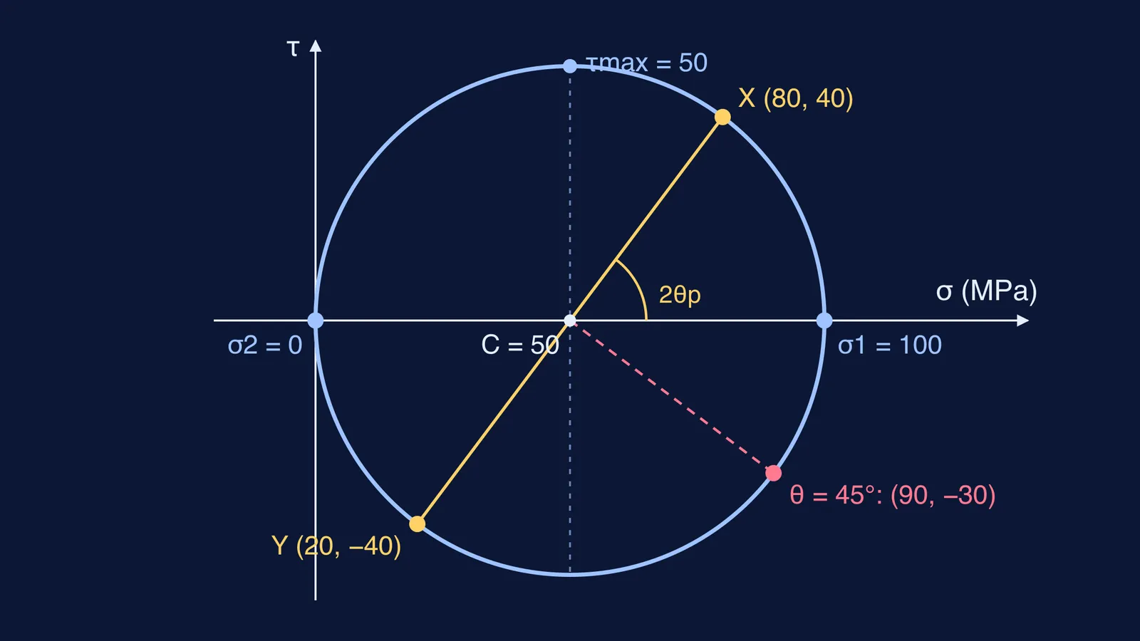
Suppose a point in a loaded plate has σx = 80 MPa, σy = 20 MPa and τxy = 40 MPa (tension positive).
Centre: C = (80 + 20) ÷ 2 = 50 MPa.
Radius: R = √(30² + 40²) = 50 MPa.
Plot X at (80, 40) and Y at (20, −40). They are opposite ends of a diameter.
Largest and smallest normal stresses: σ1 = C + R = 100 MPa and σ2 = C − R = 0.
Largest shear: τmax = R = 50 MPa, at the top and bottom of the circle.
Direction of σ1: tan 2θp = 2τxy ÷ (σx − σy) = 80 ÷ 60, so 2θp ≈ 53.1° and the real plane is turned θp ≈ 26.6°.
Check one cut at θ = 45°: the equations give σn = 50 + 0 + 40 = 90 MPa and τn = −30 MPa. Since (90 − 50)² + 30² = 50², that point sits on the circle, 90° round from X.
Because σ2 = 0, the circle touches the origin: this messy-looking mix of stresses is really one plain pull of 100 MPa along a line tilted about 26.6° from x.
One warning: textbooks differ on whether shear is plotted upward or downward, which flips the direction you travel round the circle (Mohr's circle, Wikipedia). Pick your course's convention and keep it.
Why do engineers still use Mohr's circle?
Mohr also used the circle to propose an early theory of strength based on shear stress, and his name lives on in the Mohr–Coulomb theory, the Maxwell–Mohr method and the Williot–Mohr diagram for trusses (Wikipedia's biography of Mohr). The circle shows the worst plane at a glance, before any trigonometry.
Heading for civil or mechanical engineering? Mohr's circle links the stress-strain curve of a wire from Class 11 to design questions such as why beams have an I-shaped cross section. Our guide on how to become a structural engineer in India shows where these courses come in.
The doubled angle is easier to see than to read; the Fermi Simulation Lab has interactive simulations for ideas like that. For practice, the Fermi Problem Library has worked problems with a step-by-step solver that explains the reasoning rather than printing an answer. Start with the example above: set τxy to 0 and predict the circle before you draw it.