
On this page
Before you can find a balancing length, you need the potential gradient. When a rheostat sits in series with the driver cell, that means working out the current first. Here is that step done slowly, then the full numerical.
What is the potential gradient of a potentiometer wire?
The potential gradient is the fall in potential per unit length of the potentiometer wire. A university lab manual from BIT Mesra puts it compactly: the gradient has the value ir, where r is the resistance per unit length of the wire and i is the current through it. It also says the current, and so the gradient, is controlled by the rheostat.
So the potential difference across any length l of wire is k × l, where k is the gradient in volts per metre. At balance, the same manual notes, no current flows through the galvanometer, so the test cell's emf equals k × l.
How does a series rheostat change the potential gradient?
The driver cell, the rheostat and the wire form one loop. In series, "the current is the same through each resistor" and the equivalent resistance is the sum of the individual resistances (OpenStax University Physics, 10.2). For a source with internal resistance r, the current is I = ε/(r + R) (OpenStax University Physics, 10.1).
Putting those together, with wire resistance R_w, wire length L, rheostat R_h and driver internal resistance r:
current in the wire: I = E / (R_w + R_h + r)
potential difference across the whole wire: V = I × R_w
potential gradient: k = V / L = E × R_w / [(R_w + R_h + r) × L]
More rheostat resistance means less current, a smaller gradient and a longer balancing length for the same test cell.
Worked numerical: gradient first, then balancing length
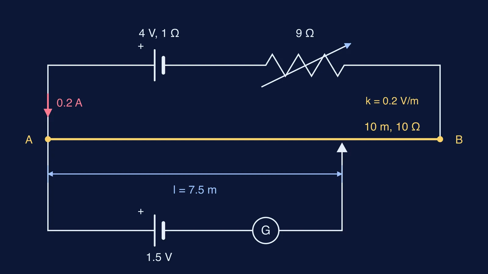
A driver cell of emf 4 V and internal resistance 1 Ω is connected in series with a rheostat set to 9 Ω and a 10 m potentiometer wire of resistance 10 Ω. Find the potential gradient, and the balancing length for a test cell of emf 1.5 V.
Total resistance in the main loop: 10 + 9 + 1 = 20 Ω.
Current: I = 4 / 20 = 0.2 A.
Potential difference across the wire: 0.2 × 10 = 2 V. The rheostat and internal resistance take the other 2 V.
Potential gradient: k = 2 V / 10 m = 0.2 V/m.
Balancing length: l = 1.5 / 0.2 = 7.5 m, that is, 750 cm from the end where the positive terminals meet.
Now take the rheostat out. The current becomes 4 / 11 ≈ 0.364 A, the wire gets about 3.64 V, k ≈ 0.364 V/m, and the same cell balances at about 4.13 m. The rheostat nearly doubled the balancing length. A reading error of a few millimetres is a smaller fraction of 7.5 m than of 4.13 m, which is why a lower gradient gives a more precise reading. Our post on how a longer wire makes a potentiometer more sensitive works through the same idea from the wire's side.
Why is there no null point, and how do you fix it?
A null point exists only if the potential difference across the whole wire is larger than the test emf. Push the rheostat in the example up to 29 Ω: the current falls to 4 / 40 = 0.1 A, the whole wire carries only 1 V, and a 1.5 V cell cannot balance anywhere. Working backwards, the wire needs at least 1.5 V, so I must be at least 0.15 A and the total resistance at most 26.7 Ω. That caps the rheostat at about 15.7 Ω.
The BIT Mesra manual gives the bench check: touch the jockey alternately at two points on the wire (A and C in its procedure) and make sure the galvanometer deflections are in opposite directions; if not, adjust the rheostat and repeat. One-sided deflection usually means the gradient is too small or the positive terminals are not joined at the same end.
A checklist for any series-rheostat potentiometer problem
List every resistance in the driver loop, including internal resistance.
Find the current before anything else.
Multiply by the wire's resistance, not the total, to get the voltage on the wire.
Divide by the wire's length, and keep the units (V/m or V/cm) consistent.
Check that the wire's total voltage exceeds the test emf before you divide.
Once the gradient is right, the standard follow-ups become one-line steps: comparing the emf of two cells and finding a cell's internal resistance with a potentiometer.
If your answer keeps coming out wrong and you cannot see which step slipped, the Fermi Problem Library has worked problems with a step-by-step solver that explains the reasoning rather than printing an answer. If potential falling along a wire still feels shaky, rebuild it in the Fermi Concept Library.