

On this page
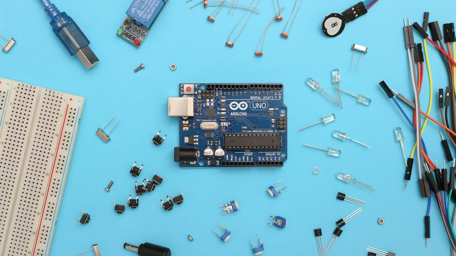
You have an idea for a school project: a night lamp that switches on in the dark, or a buzzer that beeps when someone opens the door. Before you spend your pocket money on an Arduino, a breadboard and a bag of resistors, you can build the whole thing in a browser tab, run the code and see whether it works. If you wire it wrong, nothing burns out.
Which free tools can simulate circuits online?
Three browser-based simulators cover most school projects:
Tinkercad Circuits (from Autodesk) is a browser-based circuit simulator that supports Arduino Uno, micro:bit and ATtiny boards, and you can program it with graphical code blocks or text code, according to its Wikipedia entry.
Wokwi is an online electronics simulator for Arduino, ESP32, STM32, Raspberry Pi Pico and many sensors, as its documentation describes.
Falstad Circuit Simulator draws an animated schematic: green means positive voltage and moving yellow dots show current, as its home page explains. It shows a schematic rather than a breadboard, but it is a clear way to watch a circuit behave.
A simple rule: use Tinkercad or Wokwi when there is code and a breadboard; use Falstad when you want to understand why the circuit does what it does.
Does practising on a simulator actually help with real circuits?
A widely cited test comes from a 2005 study by N. D. Finkelstein and colleagues at the University of Colorado Boulder, published in Physical Review Special Topics: Physics Education Research. In an introductory physics course, one group did the DC circuit lab with real bulbs, meters and wires, another used a computer simulation that showed electron flow, and a third group from another course had no lab. According to the paper's abstract, the simulation group outperformed the others both on a conceptual survey and in assembling a real circuit and explaining how it worked.
That was one course and one topic, so read it as "a simulator is a good place to start", not "you never need real parts".
Worked example: will this LED circuit damage your Arduino?
The classic first project is an LED on a digital pin. Two Arduino facts decide whether it is safe.
An Arduino (ATmega) output pin can source or sink up to 40 mA, and short circuits or high-current loads can destroy the pin, says the Arduino digital pins guide.
A red LED typically drops 1.8 to 2.2 volts, and the Arduino Blink tutorial uses a 220-ohm resistor on the 5 V Uno, according to the Arduino Blink example.
Now use Ohm's law on the resistor, which carries the voltage the LED does not take:
Voltage across the resistor: 5 V minus 2.0 V = 3.0 V.
Current: I = V / R = 3.0 / 220 = 0.0136 A, about 13.6 mA.
Across the LED's range (1.8 to 2.2 V), the current is 12.7 to 14.5 mA, comfortably below 40 mA.
Swap in a 1 kΩ resistor: 3.0 / 1000 = 3 mA. Dimmer, but the same Arduino tutorial says LEDs stay visible up to about 1 kΩ on a 5 V board.
Now check it in Tinkercad: put the virtual multimeter in series, set it to current, start the simulation and compare the reading with your 13.6 mA. Then delete the resistor and see what happens.
If the Ohm's law step is the shaky part, the Fermi Problem Library has worked problems with a step-by-step solver that explains the reasoning rather than printing an answer.
A five-step plan to test before you buy
Sketch it on paper. Draw the schematic and label every node.
Predict. Work out each current and what the code should do.
Build it exactly as you will on the desk. Same breadboard layout, pins and resistor values.
Measure, then break it on purpose. Read currents with the virtual multimeter, then reverse the LED and note what changes.
Turn the parts list into a shopping list. Copy every component and value from your working design, plus a spare of the cheapest parts.
What can a simulator not tell you?
A browser cannot catch a loose jumper wire, a worn breadboard strip, a resistor with the wrong colour bands, or a sensor that behaves differently in a bright classroom. When your parts arrive, check them with a meter. Our guide to using a multimeter for resistance and continuity and our walkthrough on how to identify a diode, LED, transistor and resistor cover that bench step.
Some ideas are hard to picture even with a breadboard in front of you, such as why current is the same at every point in a series loop. The Fermi Simulation Lab has interactive simulations for ideas that are easier to see than to read.
Once your design works on screen and on the desk, look at these robotics competitions for school students in India for where to take it next.