
On this page
If your practical file has the line "To identify a diode, an LED, a resistor and a capacitor from a mixed collection of such items", you are doing a standard Class 12 physics activity. The CBSE Physics curriculum for 2026-27 lists it as the first Section B activity. The second asks you to use a multimeter to see one-way current through a diode and an LED, and to check whether a component works. In that document's 30-mark practical scheme, one activity carries 3 marks and the viva carries 5.
The NCERT Class 12 Physics Laboratory Manual version adds a transistor and an IC. The CBSE list does not name them, but this guide covers all six.
What does each component do on a multimeter?
These definitions come from Activity 8 of the NCERT manual:
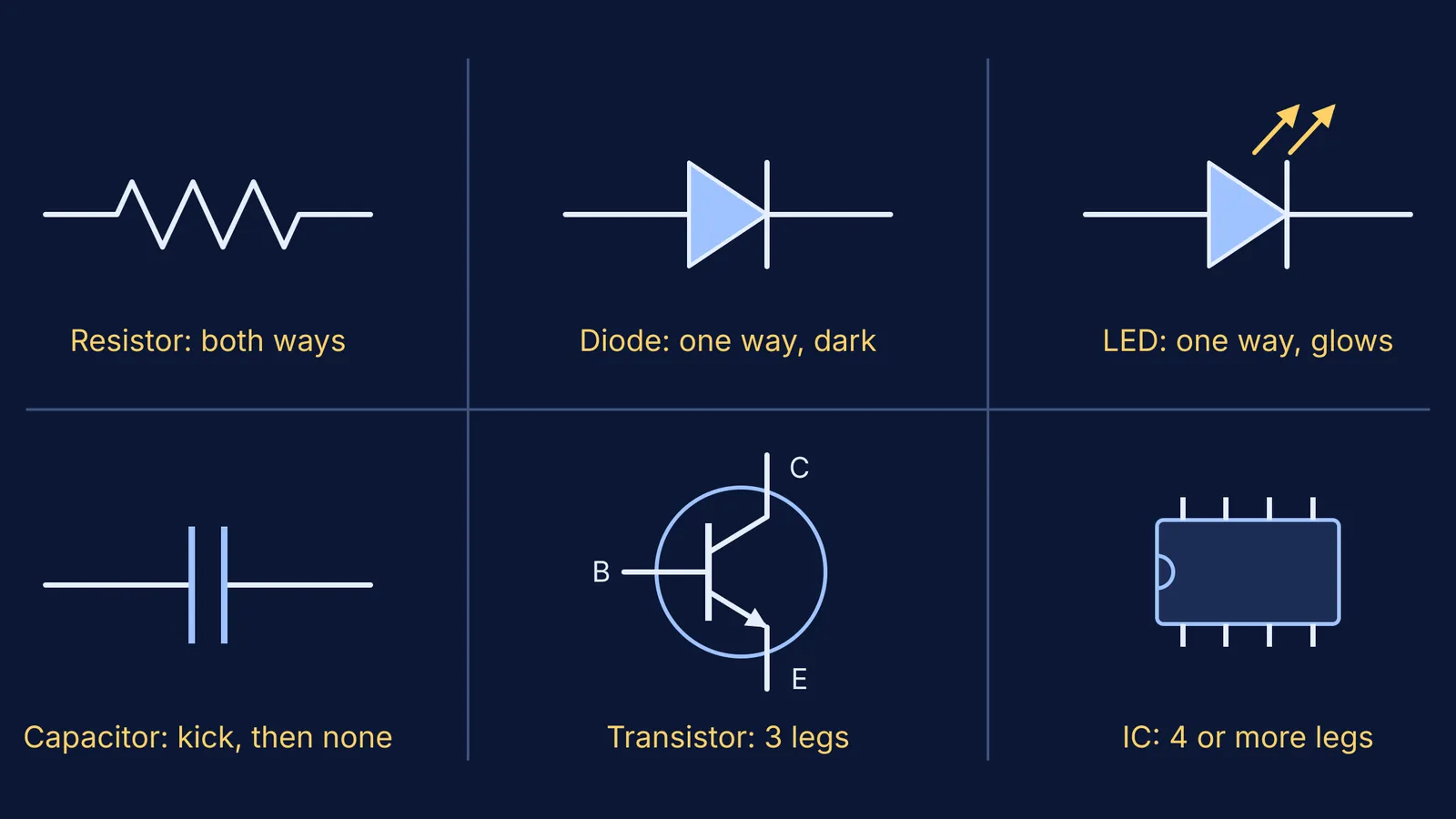
A resistor conducts equally in both directions.
A diode conducts only when forward biased, and gives no light.
An LED (light emitting diode) conducts only when forward biased, and emits light while conducting.
A capacitor does not conduct, but stores some charge when a dc voltage is applied.
A transistor has three terminals: emitter (E), base (B) and collector (C).
An IC is a multi-terminal chip, though a few, such as the 7805, have three.
How do you identify a diode, LED, transistor and resistor step by step?
The NCERT procedure, in bench order:
Label each item A, B, C and note its number of legs.
Four or more legs on a black rectangular block: IC. Three legs: probably a transistor (test below).
For two legs, look first. Three colour bands then a silver or gold band: resistor. A silver ring marks a diode's n-side; an LED's shorter leg is usually the n-side.
Set resistance mode on the highest range, touch the leads to the legs, then swap them.
Equal both ways: resistor. One way, with light: LED. One way, no light: diode. Neither way: capacitor (a large one may kick briefly first).
NCERT's precautions make easy viva answers: clean the leads, zero an analog meter, and avoid touching the metal ends of the leads while measuring, or your body's resistance sits in parallel with the part.
On an analog meter in resistance mode, the manual notes, the black lead connects to the internal 3 V battery's positive. On a digital meter's diode test, the red lead is positive, says Fluke's guide to testing diodes.
What readings should a digital multimeter show?
On the diode-test setting, a good silicon diode shows a forward voltage drop of 0.5 to 0.8 V and shows OL when reversed, according to Fluke. Germanium diodes read about 0.2 to 0.3 V; our post on why silicon is preferred over germanium for diodes explains why. A diode that reads the same both ways is shorted, and one that shows OL both ways is open.
On resistance mode, the NCERT manual says a forward-biased diode reads from a few ohms to kilohms, and a reverse-biased one of the order of megaohms.
How do you test a transistor's legs with a multimeter?
There is no universal pin diagram for transistors, the NCERT manual says; check the data sheet, or a dot that marks the emitter on some. Without either, find the base: it is the one leg that gives low resistance to both others with the same meter lead kept on it.
n-p-n: positive on the base and the other lead on E or C gives low resistance; reversed, very high.
p-n-p: the opposite, so negative on the base gives the low readings.
Low resistance both ways between two legs means a shorted junction: not in working order.
A worked example, with made-up readings: positive on leg 2, other lead on leg 1 or leg 3: low. Swap the leads on both pairs: very high each time. Leg 2 is the base, and the transistor is n-p-n.
How do you read resistor and capacitor markings?
The NCERT manual gives the colour code as black 0, brown 1, red 2, orange 3, yellow 4, green 5, blue 6, violet 7, grey 8, white 9. Its own example, red-violet-orange-silver, reads 2, 7 and three zeros: 27 000 ohm at ±10%. Gold means ±5%, and a resistor with only three bands has a tolerance of ±20%.
Many ceramic capacitors use a three-digit code from the IEC 60062 standard; Vishay's ceramic capacitor information sheet shows codes 104 to 914 covering 100 nF to 910 nF. The rule: write the first two digits, add as many zeros as the third digit says, and read picofarads: 104 is 100 000 pF, or 0.1 µF. Tolerance letters: J is ±5%, K ±10%, M ±20%.
If the p-n junction behind one-way conduction feels shaky, the Fermi Concept Library gives every physics concept its own lesson to revise before the viva. Next, practise finding a diode's dynamic resistance from its I-V graph, or see our week-by-week plan for board practicals and JEE Main.