

On this page
If you connect a standard carbon resistor to a battery and measure the current, the result is a straight line through the origin. Because the line is straight, the resistance (R = V/I) is the same everywhere. But a p-n junction diode is different. It is a non-ohmic device, meaning its current-voltage (I-V) graph is a curve.
Because the slope of this curve changes constantly, you cannot find the resistance just by dividing the total voltage by the total current. Instead, you have to measure the dynamic resistance, which is the resistance the diode offers to tiny changes in voltage around a specific operating point.
What is the difference between static and dynamic resistance?
When dealing with a diode, we define two different types of resistance:
Static Resistance (R): This is the simple ratio of voltage to current (R = V/I) at one specific point on the curve. It represents the resistance a diode offers to a steady direct current (DC).
Dynamic Resistance (r): This is the ratio of a small change in voltage (ΔV) to the resulting small change in current (ΔI). It represents the resistance the diode offers to a fluctuating alternating current (AC) signal.
The mathematical formula for dynamic resistance is: r = ΔV / ΔI.
If you are struggling to picture why resistance changes when a curve is not a straight line, Fermi's AI tutor can draw the graph and check your understanding as it goes.
How to find the dynamic resistance of a diode from its I-V graph?
To find the dynamic resistance, you need to calculate the reciprocal of the slope of the I-V curve at your chosen operating point. Here is the step-by-step method:
Locate the operating point: Find the specific voltage or current on the curve where you need the resistance.
Pick two close points: Select two points on the curve that bracket your operating point closely (e.g., V₁ and V₂ with their corresponding currents I₁ and I₂).
Find the differences: Calculate the change in voltage (ΔV = V₂ − V₁) and the change in current (ΔI = I₂ − I₁).
Divide them: Divide ΔV by ΔI. Ensure you convert the current from milliamperes (mA) to amperes (A) before calculating to get the answer in ohms (Ω).
If you need more practice with graph-based problems, read our guide on photodiode, LED and solar cell I-V curves for JEE Main.
A worked example from Class 12 Physics
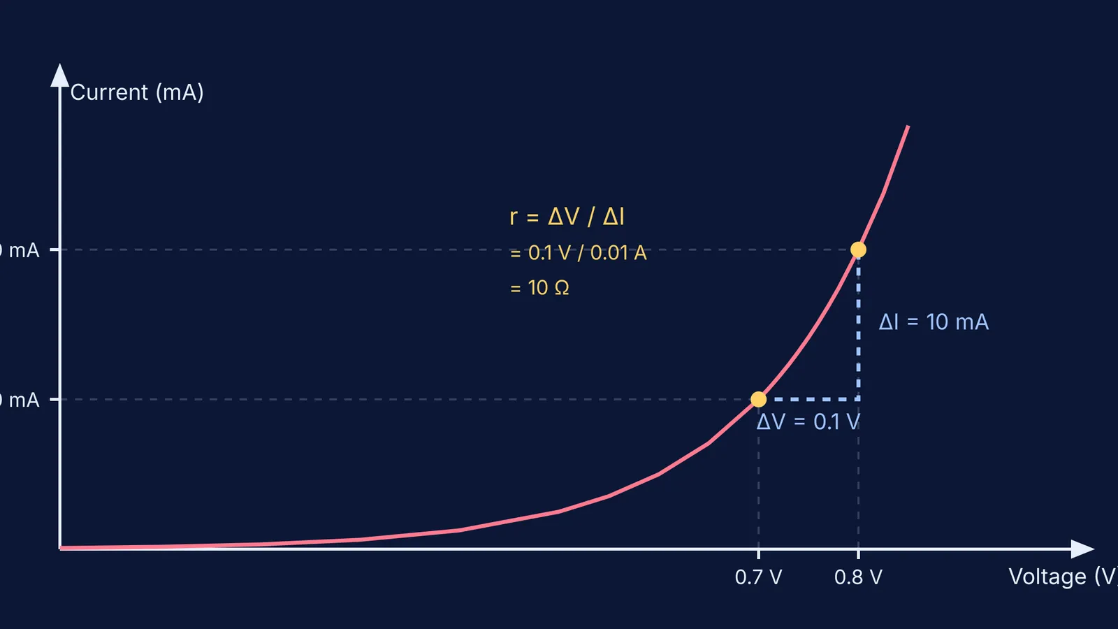
Let's look at a concrete example from the NCERT Class 12 Physics textbook, Chapter 14 (Semiconductor Electronics). Example 14.4 asks us to find the resistance of a silicon diode operating at a forward current of 15 mA.
The textbook provides a graph showing the diode's behaviour. Looking at the curve around 15 mA, we can read two exact data points:
At V₁ = 0.7 V, the current is I₁ = 10 mA.
At V₂ = 0.8 V, the current is I₂ = 20 mA.
First, we find the change in voltage: ΔV = 0.8 V − 0.7 V = 0.1 V.
Next, we find the change in current, making sure to convert to amperes: ΔI = 20 mA − 10 mA = 10 mA = 10 × 10⁻³ A = 0.01 A.
Finally, we apply the formula: r = 0.1 V / 0.01 A = 10 Ω.
The dynamic resistance at this point is 10 Ω.
Notice how different this is from the static resistance. At roughly 15 mA, the voltage is about 0.75 V. If you incorrectly calculated the static resistance (R = V/I), you would get 0.75 V / 0.015 A = 50 Ω. This is why the slope method is essential. The Fermi Problem Library has a step-by-step solver that explains the reasoning for semiconductor numericals like this, rather than just printing an answer.
For a broader look at how currents and voltages are assigned in complex circuits, explore the node potential method.
Why does dynamic resistance matter in real circuits?
In practical electronics, a diode rarely operates on just a steady DC voltage. Usually, a small, fluctuating AC signal rides on top of a steady DC bias.
The DC bias voltage sets the operating point on the I-V curve. This determines the static state. However, the small AC signal fluctuates back and forth around this point. As far as the AC signal is concerned, the diode behaves like a resistor whose value is equal to the slope of the curve at that exact spot—the dynamic resistance.
In the forward bias region (after the knee voltage), the curve is very steep. A tiny change in voltage causes a massive change in current, meaning the dynamic resistance is very low, often just a few ohms. As noted in the NCERT Class 12 Physics textbook, in the reverse bias region (before the breakdown voltage), the curve is almost perfectly flat. A change in voltage causes virtually no change in current, giving a dynamic resistance in the millions of ohms (megaohms).
Understanding this difference is critical when designing circuits where diodes handle changing signals, such as radio demodulators or audio rectifiers. You can also explore how changing the underlying material properties affects behaviour in our guide to n-type and p-type semiconductors.


