
On this page
A zener regulator is one of the few circuits where the interesting thing is what does not change. You turn the input voltage up, and the output sits still. Here is a circuit with real component values, the numbers to predict before you run it, and four tests that show where it stops working.
What does a zener diode voltage regulator do?
A zener diode is a p-n junction used in reverse bias, where breakdown holds the voltage close to a constant value called the zener voltage, according to HyperPhysics at Georgia State University. The same page notes that zener diodes can be made to break down at voltages from about 4 V to several hundred volts.
The regulator has three parts. The input feeds a series resistor R; after R, the reverse-biased zener and the load sit in parallel to ground. The output is the voltage across the load.
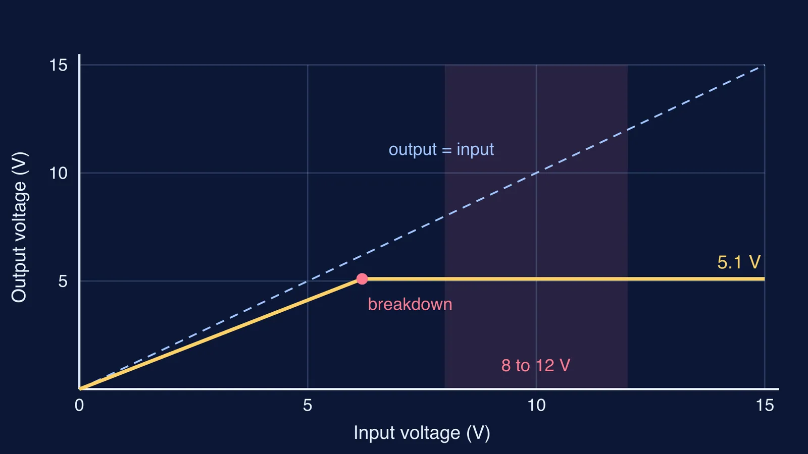
Below breakdown, the zener carries almost no current, so R and the load form a plain voltage divider. Above breakdown, the zener takes whatever extra current keeps its voltage steady, and the extra input voltage ends up across R, not across the load.
If breakdown is fuzzy, read the difference between Zener and avalanche breakdown first.
How do you set up the simulation?
We used figures from Vishay's 1N4728A to 1N4761A datasheet. For the 1N4733A, it lists a nominal zener voltage of 5.1 V at a test current of 49 mA, a typical dynamic resistance of 7 ohms, a maximum regulator current of 178 mA and a power rating of 1300 mW. The same datasheet gives a standard voltage tolerance of plus or minus 5%.
The free Falstad circuit simulator runs in a browser and shows current as moving dots. Build this:
A variable DC source, starting at 4 V.
A 47 ohm series resistor.
A zener set to 5.1 V, cathode facing the resistor.
A 220 ohm load across the zener, with a voltmeter across it.
Ammeters in series with the resistor and with the zener.
For more ideas that are easier to see than to read, try the interactive simulations in the Fermi Simulation Lab.
What should you see as you vary the input voltage?
Write your predictions first. These use the ideal model, where the zener holds exactly its datasheet value of 5.1 V once it conducts, so the load always draws 5.1 / 220, about 23.2 mA.
4 V input: the zener is off. The output is 4 x 220 / 267, about 3.3 V.
About 6.2 V input: the divider output reaches 5.1 V. This is the knee, where breakdown begins.
8 V input: resistor current is 2.9 V / 47 ohms, about 61.7 mA. The load takes 23.2 mA, so the zener takes about 38.5 mA. Output: 5.1 V.
10 V input: resistor current about 104.3 mA, zener about 81.1 mA. Output: still 5.1 V.
12 V input: resistor current about 146.8 mA, zener about 123.6 mA, so the zener dissipates about 0.63 W. Output: still 5.1 V.
Across 8 V to 12 V, the zener current more than triples, and in the ideal model the output does not move. That is regulation.
Where does a zener regulator stop working?
Run these four tests to find the edges, and compare the currents with the limits in the 1N4733A datasheet.
Too little input. Sweep down from 8 V. Below about 6.2 V the output starts falling with the input, because the zener has left breakdown.
Too much load. At 8 V, only about 61.7 mA flows through R. Lower the load below about 83 ohms, so it wants more than that, and the output sags.
No load. Remove the 220 ohm load at 12 V. All 146.8 mA now goes through the zener, about 0.75 W, still inside the datasheet's 178 mA and 1300 mW limits.
Too much input. With the load connected, the zener current reaches 178 mA near 14.6 V. Past that, a real 1N4733A is outside its rating, even if the simulation keeps going.
Why doesn't the output stay perfectly fixed?
The Vishay datasheet gives the 1N4733A a typical dynamic resistance of 7 ohms, so its voltage creeps up as its current rises. Going from 8 V to 12 V adds roughly 85 mA of zener current, and 85 mA x 7 ohms is about 0.6 V. Including R and the load brings it to around half a volt, still far smaller than the 4 V change at the input. If your simulator lets you set the zener's series resistance, compare 0 ohms with 7 ohms at 12 V input: the gap is the price of a real diode.
For the measured curve, our Zener diode reverse characteristic practical covers the circuit, readings and graph. To practise choosing R on paper, try our Zener diode regulator problems on the series resistor. If one of your simulation results surprised you, Fermi's AI tutor can run the simulation with you and ask what you expected, so you find the step where your prediction went wrong.