
On this page
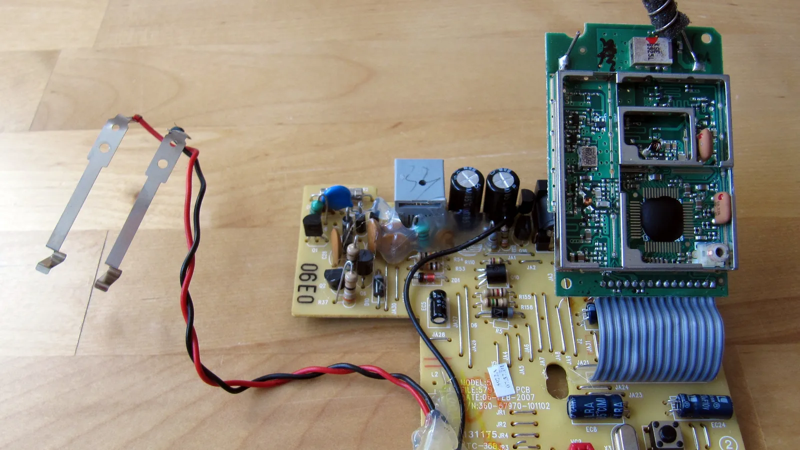
The standard circuit in broadcast radios for most of the past century, from valve sets to the family transistor radio, came from one idea by Edwin Howard Armstrong (ETHW). Instead of building an amplifier that can follow you up and down the dial, the radio moves every station to one fixed frequency and amplifies it there. Armstrong developed this circuit, the superheterodyne, while working at a laboratory in Paris for the Allied war effort during the First World War, according to his Wikipedia biography.
What problem was Armstrong trying to solve?
Early radios had to amplify weak signals at the frequency they arrived at, and that was hard with the valves of the day. The Wikipedia article on the superheterodyne notes that triode RF amplifiers had been rather unsuccessful except at very low frequencies.
Armstrong's answer is spelled out in his US patent 1,342,885, filed on 8 February 1919 and granted on 8 June 1920. The method converts the frequency of the incoming oscillations "down to some predetermined and lower value of readily amplifiable high frequency current and passing the converted current into an amplifier."
The patent was sold to Westinghouse, and RCA brought out superheterodyne Radiola sets in early 1924 (Wikipedia).
How does a superheterodyne receiver work?
A superheterodyne receiver converts the high-frequency received signal to an intermediate frequency by heterodyning it with an oscillation generated in the receiver, then amplifies that intermediate-frequency signal (ETHW).
In plain steps:
Antenna and RF stage: picks up many stations and makes a rough first choice.
Local oscillator: a small circuit inside the radio makes its own steady wave. Turning the tuning knob changes this frequency.
Mixer: a nonlinear device combines the station with the oscillator. Out come the sum and the difference of the two frequencies.
IF amplifier and filter: tuned once, at the factory, to the difference frequency. Only the station whose difference lands here gets through.
Detector: pulls the audio back out of the amplified signal.
Standard intermediate frequencies include 455 kHz for medium-wave AM receivers and 10.7 MHz for broadcast FM (Wikipedia). Because the IF stages never change frequency, they can be carefully adjusted for best performance, a process called alignment. The same article explains the division of labour: the RF circuits make a broad first selection, and the IF stages provide most of the amplification and selectivity.
Worked example: tuning an AM radio to 1000 kHz
Take a medium-wave radio with the standard 455 kHz IF. Broadcast receivers usually place the oscillator above the station, which the superheterodyne article calls high-side injection.
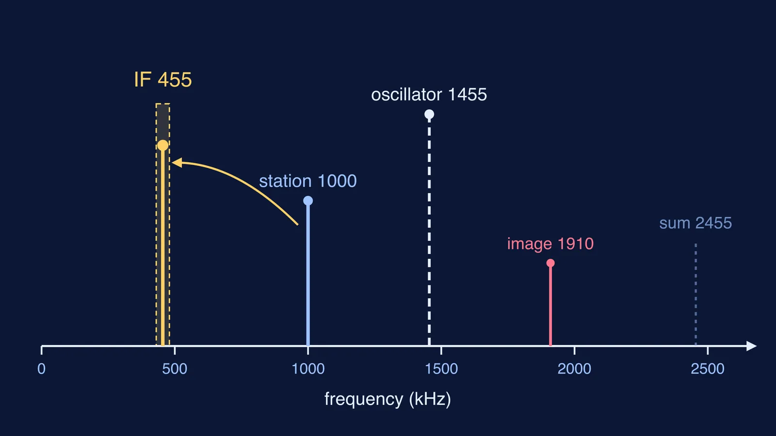
You want a station at 1000 kHz, so the oscillator runs at 1000 + 455 = 1455 kHz.
The mixer produces 1455 − 1000 = 455 kHz (kept) and 1455 + 1000 = 2455 kHz (filtered out).
Turn the dial to a station at 600 kHz. The oscillator moves to 1055 kHz, and the difference is again 455 kHz.
The IF amplifier never knows which station you picked. It always sees 455 kHz.
Why do sum and difference appear at all? Multiply two waves and use the identity sin A sin B = ½[cos(A − B) − cos(A + B)]. A mixer is, roughly, a circuit that multiplies. The difference term is the same arithmetic as acoustic beats, which we explain in beats versus interference of sound.
What is the image frequency, and why does it matter?
There is a catch. With the oscillator at 1455 kHz, a station at 1455 + 455 = 1910 kHz also gives a 455 kHz difference. This unwanted signal, offset from the wanted one by twice the IF, is called the image frequency (Wikipedia).
The IF filter cannot remove it, because by then it sits at exactly 455 kHz. So the RF stage before the mixer must block it. That is why the first selection, though rough, still matters.
How can you connect this to your physics syllabus?
The superheterodyne ties together three ideas from Class 11 and 12 physics:
Beats: two close frequencies produce a difference frequency.
Resonance: each IF stage is a tuned circuit that responds strongly near one frequency. Our series LCR resonance simulation shows how sharply the current peaks.
Modulation: the station carries audio on a carrier wave, the idea behind Reginald Fessenden's first voice radio broadcast.
A quick practice plan: redo the worked example for three stations of your choice, write down the oscillator, sum, difference and image each time, then sketch them on one frequency axis. If the mixing step still feels abstract, the Fermi Simulation Lab has interactive simulations for ideas that are easier to see than to read, and the Fermi Concept Library gives each concept, such as resonance, its own lesson.
Draw Armstrong's frequency axis once by hand and you will see why the idea lasted.