On this page
Sweep the frequency of the AC source in a series LCR simulation and the current traces out a hill. If you can say where the peak will be, how tall and how wide, before you touch the slider, you understand resonance. Here is how, with a worked example you can check in any circuit simulation.
What is the resonant frequency of a series LCR circuit?
Each component holds back the current in its own way. The inductive reactance is X_L = ωL, the capacitive reactance is X_C = 1/(ωC), and the circuit's total impedance is Z = √(R² + (X_L − X_C)²) (OpenStax University Physics Volume 2, section 15.3).
X_L rises with frequency and X_C falls, so at one frequency they are equal. Setting ωL = 1/(ωC) gives the resonant angular frequency ω₀ = 1/√(LC), or f₀ = 1/(2π√(LC)) (OpenStax, section 15.5). R does not appear in the formula, so changing the resistance never moves the peak.
Why does current peak at resonance?
At f₀ the two reactances cancel, so the impedance drops to its smallest possible value: Z = R. The current amplitude is then I₀ = V₀/R, the largest this source can drive, and the average power delivered is also at its maximum (OpenStax, section 15.5). HyperPhysics sums it up: series resonance is "characterized by minimum impedance and zero phase" (HyperPhysics, series RLC resonance).
Below f₀ the capacitor's reactance is larger. Above f₀ the inductor's is. On either side some reactance is left over, so Z is bigger than R and the current is smaller.
How does resistance change the sharpness of resonance?
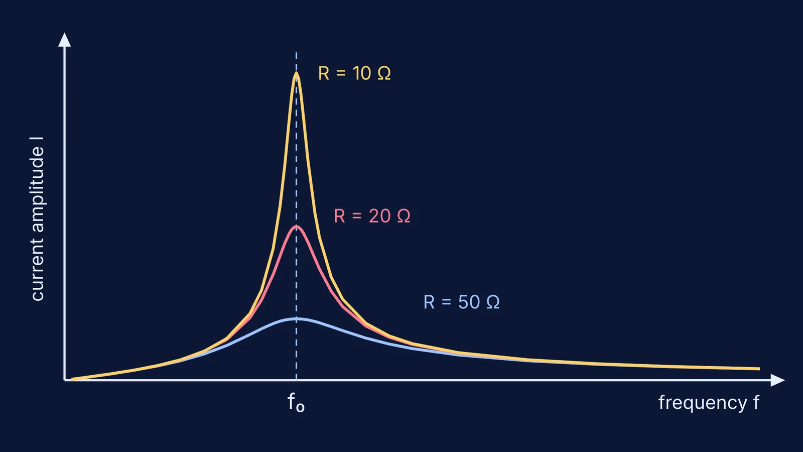
Resistance sets how tall and how narrow the peak is, not where it sits. The quality factor is Q = ω₀L/R, and the width of the resonance is Δω = R/L (HyperPhysics). A smaller R gives a taller, narrower peak. OpenStax defines the bandwidth as the range of frequencies over which the average power is more than half its maximum, and notes that a narrower bandwidth needs "a lower resistance or higher inductance" (OpenStax, section 15.5).
This is why tuning circuits work. HyperPhysics notes that "the sharp minimum in impedance which occurs is useful in tuning applications", and that Q values in circuit applications usually fall between 10 and 100 (HyperPhysics). For more exam-style practice on Q and bandwidth, see our guide to LCR resonance and the quality factor.
What is the phase between voltage and current?
The phase angle is φ = tan⁻¹((X_L − X_C)/R) (OpenStax, section 15.3). Its sign tells you which component is winning:
Below f₀, X_C is bigger than X_L: current leads voltage, and the circuit behaves like a capacitor.
At f₀, φ = 0: voltage and current are in phase.
Above f₀, X_L is bigger than X_C: voltage leads current, and the circuit behaves like an inductor.
Some textbooks write the fraction the other way round; the physics stays the same. If the rotating arrows behind this still feel shaky, start with how phasors work in AC circuits.
Worked example: predict, then sweep
Take L = 10 mH, C = 1 µF, R = 10 Ω and a source amplitude of 10 V. Each step below uses only the formulas from OpenStax section 15.5 and HyperPhysics.
Resonant frequency: ω₀ = 1/√(0.01 × 0.000001) = 10,000 rad/s, so f₀ = 10,000/2π ≈ 1,590 Hz.
Peak current: I₀ = 10 V ÷ 10 Ω = 1 A.
Sharpness: Q = (10,000 × 0.01)/10 = 10, and the width is Δω = R/L = 1,000 rad/s, about 159 Hz.
Off resonance at 2f₀ (about 3,180 Hz): X_L = 200 Ω and X_C = 50 Ω, so Z ≈ 150 Ω, the current is about 0.067 A, and voltage leads current by about 86°.
Now raise R to 50 Ω: the peak stays at 1,590 Hz, but I₀ falls to 0.2 A and Q falls to 2. The hill is five times lower and five times wider.
The chart at the top of this post shows this circuit at R = 10, 20 and 50 Ω.
While you sweep, check these:
Did the peak land on your predicted f₀? If not, check your units (mH and µF trip up a lot of people).
Read the phase just below and just above f₀. Does the sign flip the way you predicted?
Change only R. Which features move, and which stay put?
Change only L or only C. Does the peak shift the way 1/√(LC) says it should?
If the sweep is hard to picture from formulas alone, the Fermi Simulation Lab has interactive simulations for ideas that are easier to see than to read. Fermi's AI tutor can run the simulation alongside you and check your understanding as it goes. For more on why simulations help with circuits, read our guide to learning circuits with simulations.
Pick one set of L, C and R values tonight, predict the five numbers above, then sweep and see how close you got.