

On this page
Most students can find the resonant frequency of an LCR circuit. Fewer can say how sharp the resonance is, why a radio picks one station and not its neighbour, or what the power factor does away from resonance. This post builds all three from one example. If phasors and impedance are new to you, start with our post on AC circuits and phasors.
What happens at resonance in a series LCR circuit?
In a series LCR circuit driven at angular frequency ω, the impedance is Z = √(R² + (X_L − X_C)²), with X_L = ωL and X_C = 1/(ωC). The NCERT Class 12 chapter Alternating Current shows that when X_L = X_C, Z is smallest and equal to R, so the current amplitude is largest. That happens at ω₀ = 1/√(LC). NCERT adds that resonance needs both L and C; an RL or RC circuit cannot resonate.
The JEE (Main) 2026 syllabus lists "LCR series circuit, resonance, power in AC circuits, wattless current" in Unit 14, and the JEE (Advanced) 2026 syllabus lists LCR (in series) circuits with a.c. sources. The quality factor is not named in either syllabus, so treat it as a tool for understanding resonance rather than a listed topic.
What are the quality factor and bandwidth?
Power peaks at ω₀, but a real circuit also passes frequencies near it. OpenStax University Physics defines the bandwidth Δω as the range of ω over which the average power is more than half its maximum. The sharpness of the peak is the quality factor:
Q = ω₀/Δω
Q = ω₀L/R, which is the same thing, since Δω = R/L
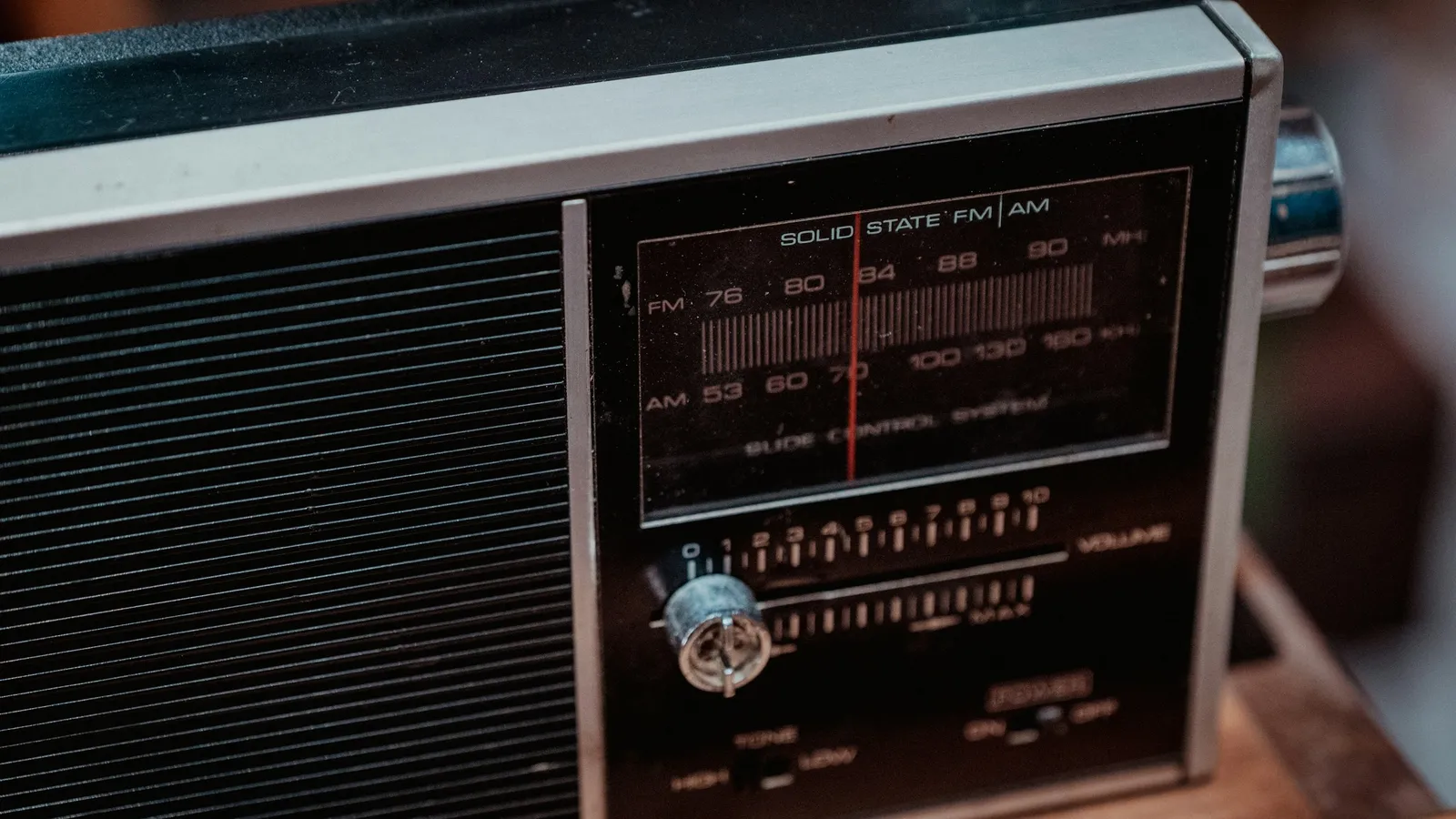
A high Q means a narrow, tall peak. OpenStax gives the radio example: a high-Q tuning circuit has a small bandwidth, so stations at slightly different frequencies meet a high impedance and are not passed.
Worked example: one circuit, all the quantities
A series circuit has R = 10 Ω, L = 0.10 H and C = 10 μF, driven by a 10 V (rms) source of variable frequency.
Resonance. ω₀ = 1/√(0.10 × 10 × 10⁻⁶) = 1/√(10⁻⁶) = 1000 rad/s, so f₀ = 1000/(2π) = 159 Hz.
Current and power at resonance. Z = R = 10 Ω, so I = 10/10 = 1.0 A and P = I²R = 10 W.
Quality factor. Q = ω₀L/R = 1000 × 0.10/10 = 10.
Bandwidth. Δω = R/L = 10/0.10 = 100 rad/s, about 15.9 Hz. The half-power points are near 951 rad/s and 1051 rad/s, where the power drops to 5 W.
Voltage across L at resonance. V_L = I × ω₀L = 1.0 × 100 = 100 V, ten times the source voltage. In a series circuit V_L at resonance equals Q times the supply voltage; V_C is the same size and opposite in phase, so they cancel in the total.
Now lower R to 2 Ω. Q rises to 50 and Δω falls to 20 rad/s. The peak is five times narrower.
What does the power factor tell you?
NCERT writes the average power as P = V I cos φ, with cos φ = R/Z, and calls cos φ the power factor. At resonance Z = R, so cos φ = 1 and all the supplied power goes into R. If R is zero, cos φ = 0, no power is used, and NCERT calls the current wattless.
Away from resonance. Drive the same circuit at ω = 1100 rad/s.
X_L = 1100 × 0.10 = 110 Ω and X_C = 1/(1100 × 10 × 10⁻⁶) = 90.9 Ω.
Z = √(10² + 19.1²) = 21.6 Ω, so cos φ = 10/21.6 = 0.46.
I = 10/21.6 = 0.46 A, and P = V I cos φ = 10 × 0.46 × 0.46 = 2.2 W.
A 10% change in frequency cut the power from 10 W to about 2 W. That is what Q = 10 looks like. NCERT also explains why a low power factor matters in power lines: it means a larger current for the same power, and so more loss in transmission. Capacitors are added to bring the power factor closer to 1.
Common mistakes and how to avoid them
Mixing ω and f. ω₀ = 1/√(LC) is in rad/s. Divide by 2π for hertz.
Defining bandwidth with half the current. The half-power points are where the current is 1/√2 of its peak, not half.
Using peak values in P = V I cos φ. Use rms values, or include a factor of 1/2 with peak values.
Thinking V_L cannot exceed the supply. At resonance it can be many times larger.
Writing cos φ = X/Z. The power factor is R/Z.
For the energy stored in the inductor, our post on self and mutual inductance is a useful companion.
A practice routine
For three circuits, compute ω₀, Q and Δω, then sketch the power curve to scale.
Change only R in each circuit and predict how Q and Δω change before calculating.
Solve two power-factor problems off resonance, one above ω₀ and one below.
Explain in two sentences why a tuning circuit needs a high Q.
When you understand the formulas but cannot picture the peak, the Fermi Simulation Lab has interactive simulations for ideas that are easier to see than read, so you can watch how a curve changes as you vary a quantity.
Today, redo the worked example at ω = 900 rad/s and check that the power factor comes out near 0.43.