

On this page
Most engineering colleges ask for marks. Barefoot College asks a village to choose two women, often grandmothers, and teaches them to install and repair the solar lights their village will run on. Here is how, and the physics inside the lantern they make.
What is Barefoot College?
Barefoot College is a college in Tilonia, Rajasthan (Barefoot College, 2012), founded by Bunker Roy in 1972, according to a 2009 profile in WIPO Magazine. Roy believed the solutions to rural poverty lie within the community, the profile explains.
Solar is central to its work. In the college's own words, "Women are trained to become solar engineers and to electrify their villages" (Barefoot College). Its website says its programmes run in more than 90 countries in the Global South.
How does Barefoot College train women as solar engineers?
Each village chooses two women in their mid to late 40s, guided by a college committee, and sends them to Tilonia for six months of training, WIPO Magazine reported. Many are semi-literate or illiterate.
Trainees identify parts by shape and colour and follow mimed, demonstrated instructions. A 2012 CNN report reposted by the college says classes are taught mainly with sign language and colour-coded circuits.
According to WIPO Magazine, the women learn to handle charge controllers and inverters, install solar panels and link them to batteries, build solar lanterns and set up a village workshop for repairs. By December 2007, the same profile says, Indian Barefoot solar engineers had made 4,100 solar lanterns, and 574 villages and hamlets had solar electricity.
In that 2012 CNN report, Roy said the college had trained 150 grandmothers from 28 countries and electrified around 10,000 houses (Barefoot College, 2012). In a 2020 application to MIT Solve, the college reported over 2,500 women trained; both are the college's own counts.
"It is unimaginable for me as an illiterate woman to be able to install solar-powered lighting in my community," says Laiku Lama, a solar programme participant from Nepal, quoted on the Barefoot College website.
How does a solar lantern circuit work?
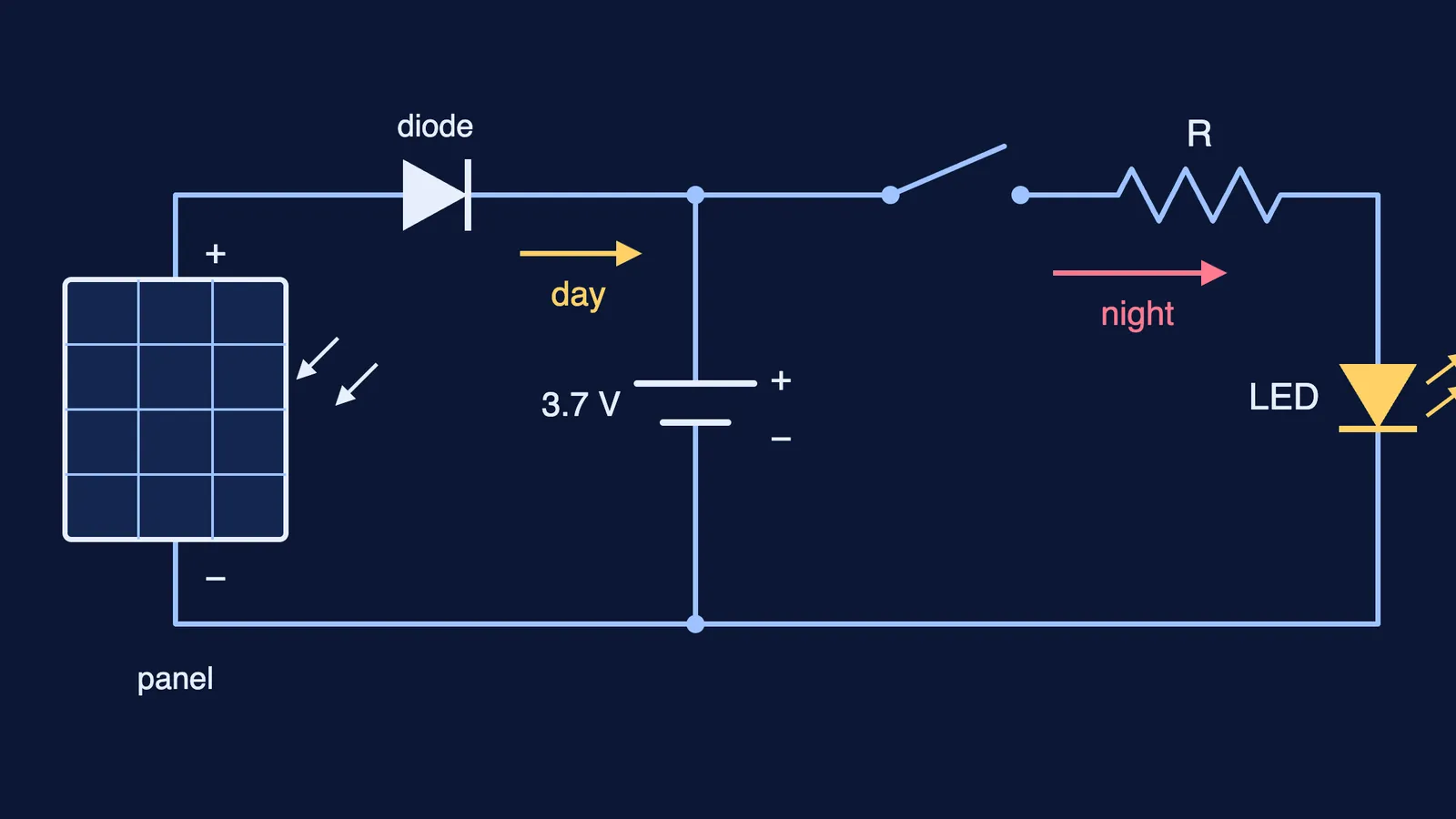
A solar lantern has four main parts: a solar panel, a charge controller, a rechargeable battery and an LED lamp (Wikipedia: Solar lamp).
By day, the panel charges the battery. A solar cell turns light directly into electricity through the photovoltaic effect, and a single silicon cell gives an open-circuit voltage of only about 0.5 to 0.6 V (Wikipedia: Solar cell). So a panel strings cells in series. Seven cells at 0.55 V give 3.85 V, but only with no current flowing, so charging a 3.7 V battery takes more cells.
At night the panel's voltage falls below the battery's, and current could flow backwards through the panel. A blocking diode in series with the panel lets current flow from panel to battery but not back (Sinovoltaics). In most systems the charge controller prevents this backflow instead (AltE Store), and it can also stop the battery overcharging or draining completely (Wikipedia: Charge controller).
After dark, the battery runs the LED. An LED conducts in only one direction, and a resistor stops it drawing too much current (SparkFun).
Worked example: the resistor in a one-LED lantern
Take a lithium-ion cell, which typically has a nominal voltage of 3.6 or 3.7 V (Wikipedia: Lithium-ion battery). Pair it with a 5 mm white LED whose datasheet gives a typical forward voltage of 3.3 V at 20 mA and a maximum DC current of 30 mA (Lite-On LTW-2S3D8 datasheet).
Voltage left for the resistor: 3.7 V - 3.3 V = 0.4 V.
Resistance for 20 mA: R = V / I = 0.4 V / 0.020 A = 20 ohms.
Power: the LED takes 3.3 V x 0.020 A = 0.066 W; the resistor wastes 0.4 V x 0.020 A = 0.008 W.
Ideal running time on a 2,000 mAh cell: 2,000 mAh / 20 mA = 100 hours.
The datasheet allows a forward voltage up to 3.7 V, and battery voltage falls as it discharges, so this is a first estimate. For more practice, see how to calculate the resistor for an LED, how to work out a battery's run time and how an LED turns current into light.
If the day and night current paths are hard to picture, the Fermi Simulation Lab has interactive simulations for ideas that are easier to see than read.
What can a student learn from Barefoot College?
Try the same approach on a circuit from your Class 10 or 12 physics textbook:
Give each part a job: source (panel), store (battery), one-way gate (diode or controller), limiter (resistor), load (LED).
Trace the day path: panel, gate, battery, back to the panel.
Trace the night path: battery, switch, resistor, LED, back to the battery.
Ask what stops current going the wrong way, and when.
Do one number with V = IR, like the resistor above.
If your resistor or run-time answer comes out wrong, the Fermi Problem Library has a step-by-step solver that explains the reasoning, so you can find the step where it went off.