
On this page
A capacitor charging through a single resistor is easy: τ = RC. Put a second resistor in the circuit and many students stall. Do you add the resistors? Use only the one in series with the battery? Neither. The capacitor only "feels" one resistance, and finding it is a short, repeatable routine.
What is the time constant of an RC circuit with more than one resistor?
For a single resistor, the time constant is τ = RC, measured in seconds (OpenStax University Physics Volume 2, section 10.5).
After one time constant, a charging capacitor holds about 63.2% of its final charge, because 1 − e^(−1) = 0.632 (OpenStax).
With several resistors, the same formula works if R is the right resistance. Tony Kuphaldt's open textbook Lessons in Electric Circuits sets out the method: treat the capacitor as the load, and the time constant equals the Thevenin resistance times the capacitance (LibreTexts, Complex Circuits/16%3A_RC_and_L/R_Time_Constants/16.07%3A_Complex_Circuits)). The same page notes that a fully charged capacitor acts like an open circuit, so its final voltage is the voltage across its terminals with the capacitor removed.
If Thévenin's theorem is new to you, our post on Léon Thévenin's 1883 shortcut explains where it came from.
How do you find the resistance the capacitor sees?
Use this four-step routine on any circuit with one capacitor:
Take the capacitor out and mark its two terminals, A and B.
Replace every ideal battery with a plain wire (an ideal current source becomes a break).
Work out the equivalent resistance between A and B. This is R_Th.
Multiply: τ = R_Th × C.
For the final voltage, put the battery back, keep the capacitor out, and find the voltage between A and B. That is V_Th, the value the capacitor creeps towards.
Worked example: a capacitor charging through two resistors
A 12 V battery and a switch feed a 6 kΩ resistor (R1). After R1, the circuit splits: a 3 kΩ resistor (R2) goes to the negative terminal, and a 100 μF capacitor sits right across R2. The capacitor starts uncharged. The switch closes at t = 0. Find τ and the capacitor voltage over time.
Step 1: R_Th. Remove the capacitor. Short the battery. From the capacitor's terminals, R1 now runs straight back to the other terminal through the shorted battery, so R1 and R2 are in parallel:
R_Th = (6 × 3)/(6 + 3) kΩ = 2 kΩ.
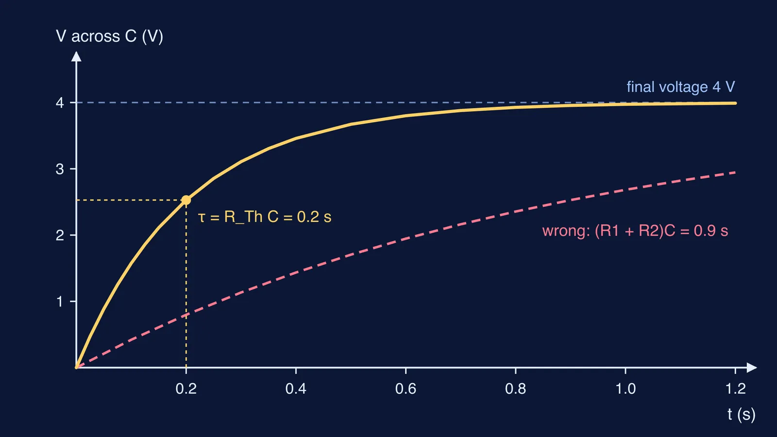
Step 2: τ. τ = 2000 Ω × 100 × 10^(−6) F = 0.2 s.
Step 3: V_Th. With the capacitor out, R1 and R2 form a voltage divider:
V_Th = 12 × 3/(6 + 3) = 4 V.
Step 4: the charging curve. V_C(t) = 4(1 − e^(−t/0.2)) volts. At t = 0.2 s, V_C = 4 × 0.632 ≈ 2.53 V. At t = 1 s (five time constants), V_C = 4(1 − e^(−5)) ≈ 3.97 V, close enough to full for most problems.
Step 5: check the ends. At t = 0, the empty capacitor acts like a wire, so it shorts R2 and the battery current is 12 V/6 kΩ = 2 mA. Long after, no current flows into the capacitor, so the battery current is 12 V/9 kΩ ≈ 1.33 mA and R2 has 4 V across it. The final 4 V across R2 matches V_Th, so the answer hangs together.
For the full single-resistor derivation of the charging and discharging equations, see our guide to RC circuits: charging, discharging and the time constant.
Why is the discharge time constant different?
Now open the switch after the capacitor has charged. The battery and R1 are cut off, so the capacitor can only discharge through R2. The resistance it sees is just 3 kΩ:
τ (discharge) = 3000 Ω × 100 × 10^(−6) F = 0.3 s.
Same capacitor, same resistors, different τ. The resistance the capacitor sees depends on which switches are open, so redo step 1 every time the circuit changes.
What are the common wrong answers for τ?
Multiple-choice options often mirror the usual slips. For the charging circuit above:
R1C = 0.6 s: using only the resistor next to the battery.
(R1 + R2)C = 0.9 s: adding resistors that are not in series as seen from the capacitor.
R2C = 0.3 s: correct for discharge, wrong for charging.
0.2 s: the resistance seen from the capacitor. This is the one.
If you would rather watch a capacitor charge, our RC circuit simulation post asks you to predict the curve before you see it.
The Fermi Simulation Lab has interactive simulations for ideas that are easier to see than to read.
When a problem has three or four resistors and you keep picking the wrong R, try it in the Fermi Problem Library, where worked problems come with a step-by-step solver that explains the reasoning rather than printing an answer.