
On this page
Any linear circuit of sources and resistors, seen from two points, can be swapped for one battery and one resistor. That shortcut is Thévenin's theorem, named after a French engineer who spent his career in the national telegraph service.
Who discovered Thévenin's theorem?
Léon Charles Thévenin was born in Meaux, near Paris, on 30 March 1857, according to a history of the equivalent circuit by Rice University engineer Don H. Johnson in Proceedings of the IEEE (2003). He graduated from the École Polytechnique and in 1878 joined Postes et Télégraphes, France's national electrical communication company, where he spent all of his career.
In 1882 he was appointed to teach courses that trained engineering inspectors, and while developing them he found new techniques, the equivalent circuit among them. In 1883 he published it in Annales Télégraphiques and, almost word for word, in the Comptes rendus of the French Academy of Sciences as "Sur un nouveau théorème d'électricité dynamique" (On a new theorem of dynamic electricity).
The road was not smooth. Thévenin asked a colleague, the mathematical physicist Aimé Vaschy, to comment on the paper, and Vaschy thought the result was incorrect. Even so, Vaschy's 1890 treatise presented the theorem under Thévenin's name and helped make it widely known. Thévenin died in Paris on 21 September 1926.
What does Thévenin's theorem say?
In modern words: any linear network of sources and resistors, seen from two terminals A and B, behaves exactly like one voltage source in series with one resistance. Engineering LibreTexts/06%3A_Analysis_Theorems_and_Techniques/6.4%3A_Thevenin's_Theorem) gives the two recipes:
Thévenin voltage (V_th): the voltage across A and B with nothing connected.
Thévenin resistance (R_th): the resistance seen between A and B after every ideal voltage source is replaced by a wire and every ideal current source by a gap.
Thévenin's own version was one formula. The current in a wire of resistance r joined across A and B is i = (V − V′)/(r + R), where V − V′ is the voltage across A and B before the wire is added and R is the network's resistance between those points (Johnson's paper prints a translation of the note). That is Ohm's law stretched to a whole network; read how Georg Ohm's law was rejected at first. Its other roots are superposition and the circuit laws of Gustav Kirchhoff.
How do you find a Thévenin equivalent?
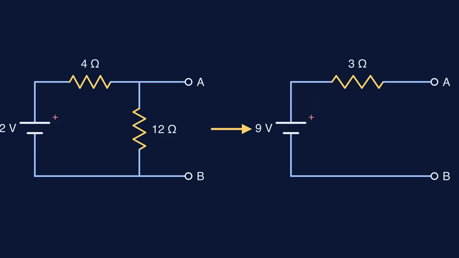
Take a 12 V cell (ignore its internal resistance) in series with a 4 Ω resistor, with a 12 Ω resistor across terminals A and B. You want the current through a load R_L joined across A and B.
Remove the load. The 4 Ω and 12 Ω form a divider: V_th = 12 × 12/(4 + 12) = 9 V.
Replace the cell with a wire. Seen from A and B, the two resistors are in parallel: R_th = (4 × 12)/(4 + 12) = 3 Ω.
Attach the load to the simple circuit: I = 9/(3 + R_L).
Now every load is one line of arithmetic:
R_L = 3 Ω gives I = 9/6 = 1.5 A
R_L = 6 Ω gives I = 9/9 = 1 A
R_L = 15 Ω gives I = 9/18 = 0.5 A
Check one the long way. With R_L = 6 Ω, the 12 Ω and 6 Ω in parallel make 4 Ω, so the cell sees 8 Ω and drives 1.5 A; the voltage across A and B is 6 V, so the load takes 1 A. Same answer, but redone for every new load. The equivalent also shows that the load takes the most power when R_L = R_th = 3 Ω, the idea behind maximum power transfer and why it wastes half the energy.
Why is it called Thévenin's theorem and not Helmholtz's?
Hermann von Helmholtz derived the same result in 1853, in a paper on electric currents in conductors applied to experiments on animal electricity, Johnson writes in Proceedings of the IEEE. In a 1950 letter that Johnson reprints, Hans Ferdinand Mayer, then a Cornell professor of electrical engineering, pointed out that Helmholtz's own example was a source with two resistors, one across the output: the shape of the example above. Mayer added that it was called "Helmholtz's theorem" in other countries. Thévenin published it 30 years later, apparently unaware of Helmholtz's work.
Johnson's verdict is that Thévenin's derivation is correct and "certainly provides more engineering insight than Helmholtz's physics-based approach". A 1940 textbook he quotes says American Telephone and Telegraph Company engineers had used it since about 1904.
How can you practise Thévenin's theorem?
Solve three networks both ways, with Kirchhoff's laws and with a Thévenin equivalent, and compare. If a step does not make sense, the Fermi Problem Library has worked problems with a step-by-step solver that explains the reasoning rather than printing an answer. If "the network seen from two points" still feels slippery, the Fermi Concept Library gives each concept its own lesson and its place in the map.
Next time a circuit looks tangled, ask what Thévenin asked: what does it look like from the two points you care about?