
On this page
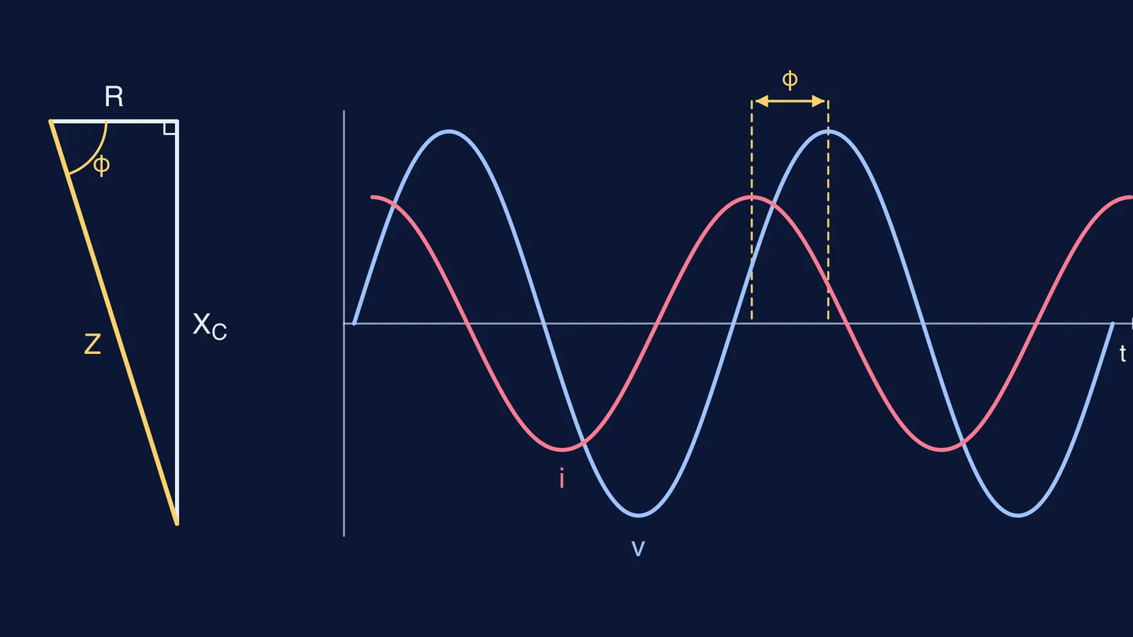
Put a resistor and a capacitor in series across an AC supply and the obvious move, adding R and Xc, gives the wrong current. The two oppose the current in different ways, a quarter of a cycle apart, so they add like the two short sides of a right-angled triangle. That triangle gives you both the impedance and the phase angle.
What is the impedance of an RC series circuit?
Impedance Z is the AC version of resistance: it is measured in ohms and captures the combined effect of resistance and reactance, as OpenStax University Physics, section 15.3 defines it.
The capacitor's opposition is its capacitive reactance, Xc = 1/(ωC) = 1/(2πfC), also measured in ohms (OpenStax, section 15.2).
The current through a capacitor leads the voltage across it by π/2 rad, a quarter of a cycle (OpenStax, section 15.2). Across the resistor, voltage and current are in phase. The same current flows through both parts of a series circuit, so the resistor voltage (I·R) and the capacitor voltage (I·Xc) sit at right angles on a phasor diagram. Add them by Pythagoras and divide by I:
Z = √(R² + Xc²)
Current: I = V/Z (use rms values on both sides, or peak values on both sides)
This is the general series LCR result, Z = √(R² + (XL − Xc)²) in OpenStax section 15.3, with no inductor, so XL = 0.
How do you find the phase angle in an RC circuit?
The phase angle φ is the angle between the supply voltage and the current, read straight off the same triangle: tan φ = Xc/R, and also cos φ = R/Z.
In an RC circuit the current leads the supply voltage, because current must flow first to build up charge on the capacitor, as the HyperPhysics RC impedance page puts it. The angle always lies between 0° (pure resistor) and 90° (pure capacitor).
If you use the LCR formula tan φ = (XL − Xc)/R from OpenStax, you get a negative angle here. The minus sign is just saying the voltage lags the current, which is the same statement as current leads voltage.
Worked example: 100 Ω and 10 μF at 50 Hz
A 100 Ω resistor is in series with a 10 μF capacitor across a 50 Hz supply. Find Xc, Z and φ.
Angular frequency: ω = 2πf = 2π × 50 ≈ 314.2 rad/s.
Convert units: 10 μF = 10 × 10⁻⁶ F = 1.0 × 10⁻⁵ F.
Reactance: Xc = 1/(ωC) = 1/(314.2 × 1.0 × 10⁻⁵) = 1/0.003142 ≈ 318.3 Ω.
Impedance: Z = √(100² + 318.3²) = √(10,000 + 101,321) = √111,321 ≈ 333.6 Ω.
Phase: tan φ = 318.3/100 = 3.183, so φ = tan⁻¹(3.183) ≈ 72.6°, with current leading.
In time, a lead of 72.6° out of 360° at 50 Hz (one cycle = 20 ms) means each current peak arrives about 72.6/360 × 20 ≈ 4.0 ms before the matching voltage peak.
Now suppose the supply is 220 V rms. The current is I = 220/333.6 ≈ 0.66 A. The resistor voltage is 0.66 × 100 ≈ 66 V and the capacitor voltage is 0.66 × 318.3 ≈ 210 V.
Those two add up to about 276 V, more than the supply. That is not an error: √(66² + 210²) ≈ 220 V, because the two voltages are 90° apart. The voltage triangle has exactly the same shape as the impedance triangle, which is why power-factor questions use cos φ = R/Z; our post on why the phase angle cuts real power picks up from here.
What mistakes do students make with RC circuits?
Using Xc = 1/(fC) and forgetting the 2π, which makes Xc about six times too big.
Leaving C in microfarads instead of farads.
Writing Z = R + Xc, the arithmetic sum.
Saying the voltage leads. In an RC circuit the current leads; voltage leads only when inductance dominates.
Taking tan⁻¹ with the calculator in radian mode and getting 1.27 instead of 72.6°.
If one of these keeps tripping you up, the Fermi Problem Library has worked problems with a step-by-step solver that explains the reasoning rather than printing an answer, so you can see exactly which line went wrong.
Try it yourself: same circuit at 100 Hz
Double the frequency and predict first: should Z and φ go up or down? Then work it out.
Xc = 1/(2π × 100 × 1.0 × 10⁻⁵) ≈ 159.2 Ω (half the 50 Hz value).
Z = √(100² + 159.2²) ≈ 188 Ω.
tan φ = 1.592, so φ ≈ 57.9°, current still leading.
Both fell, as the callout predicted. For the capacitor-only version of this problem, see current through a capacitor on AC mains, and for the full LCR picture with resonance, read AC circuits for JEE: phasors, impedance and resonance. If the idea of reactance itself still feels shaky, the capacitance and AC topics in the Fermi Concept Library each have their own lesson.