
On this page
A capacitor connected to AC mains is one of the shortest numericals in the alternating current chapter. It still costs marks, because small slips (f instead of ω, microfarads, rms against peak) give wrong answers that look believable. Here is the method, a worked example and a checklist.
What is capacitive reactance at 50 Hz?
Capacitive reactance, Xc, is the capacitor's opposition to a change in current, and it equals 1/(ωC), according to OpenStax University Physics Volume 2, section 15.2. The same source notes that it depends inversely on frequency: high frequency means low reactance.
India's grid runs at 50 Hz, and operators take measures to keep it within a band of 49.90 to 50.05 Hz, according to a Drishti IAS summary of a PIB release. So for mains problems, ω = 2π × 50 ≈ 314 rad/s, and the formula becomes:
Xc = 1/(2πfC) = 1/(314 × C), with C in farads
I rms = V rms / Xc
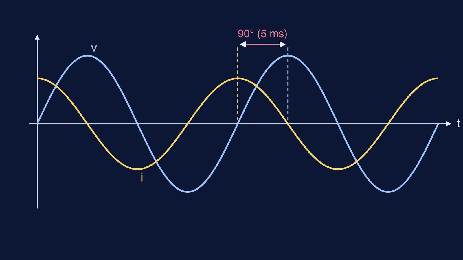
Current leads voltage by 90° (π/2)
Because Xc falls as frequency rises, doubling the frequency halves Xc and doubles the current for the same voltage. You can see the full curve in our post on how reactance changes with frequency in graphs.
How do you find the current through a capacitor connected to AC mains?
Take a typical exam version: a 10 µF capacitor is connected to a 230 V, 50 Hz supply. Find the rms current, the peak current and the phase relation.
Write the knowns in SI units: C = 10 µF = 10 × 10^-6 F = 1 × 10^-5 F, V rms = 230 V, f = 50 Hz.
Find ω: ω = 2πf = 2 × 3.1416 × 50 ≈ 314.2 rad/s.
Find Xc: Xc = 1/(314.2 × 1 × 10^-5) = 1/0.003142 ≈ 318 Ω.
Find the rms current: I rms = 230/318 ≈ 0.72 A.
Find the peak current if asked. OpenStax gives I rms = I0/√2 in section 15.4 on power in AC circuits, so I0 = 0.72 × 1.414 ≈ 1.02 A. The peak voltage is 230 × 1.414 ≈ 325 V.
State the phase: if v = 325 sin(314t) volts, then i = 1.02 sin(314t + π/2) amperes. The current reaches its peak a quarter cycle, 5 ms, before the voltage does.
The 230 V is already an rms value: OpenStax notes that alternating voltages are usually described by their rms values, and that a household outlet's rated voltage is one. So divide it by Xc directly.
Why does the current lead the voltage by 90 degrees?
The current into a capacitor is the rate at which its charge changes, and charge follows voltage (q = Cv). So the current is largest when the voltage is changing fastest, which is when the voltage crosses zero. It is zero when the voltage sits at its peak and is momentarily not changing. That puts the current peak a quarter cycle ahead of the voltage peak. OpenStax states it directly: the current through a capacitor leads the voltage by π/2 rad, or a quarter of a cycle (section 15.2).
A common one-mark follow-up: the average power taken by an ideal capacitor is zero, because it absorbs energy during one half-cycle and returns it during the other (OpenStax section 15.4).
If the phase picture is hard to hold in your head, the Fermi Simulation Lab has interactive simulations for ideas that are easier to see than to read.
Which mistakes cost marks in this numerical?
Check your working against this list before boxing the answer:
f instead of ω. Xc = 1/(ωC), with ω = 2πf (OpenStax section 15.2). Writing Xc = 1/(fC) gives 1/(50 × 10^-5) = 2000 Ω and a current of only 0.115 A. The 2π is missing, so the answer is 6.28 times too small.
Microfarads left unconverted. Using C = 10 instead of 10^-5 F makes Xc absurdly small. If your current comes out in kiloamperes, check the µ.
Peak and rms mixed up. Treating 230 V as peak gives 0.51 A rms instead of 0.72 A. Mains voltages are rms unless the question says peak; see our post on the peak value of 220 V mains.
Phase in the wrong direction. In a capacitor the current leads. The mnemonic CIVIL helps: in C, I comes before V.
Adding reactance to resistance directly. With a bulb or resistor in series you need impedance, Z = √(R² + Xc²), not R + Xc. Our worked post on a bulb and capacitor in series on AC shows why.
If you keep landing on the wrong number and cannot see which step slipped, try a similar question in the Fermi Problem Library. It has worked problems with a step-by-step solver that explains the reasoning rather than printing an answer.
Next step: redo the example with a 4 µF capacitor on 230 V, 50 Hz. You should get Xc ≈ 796 Ω and I rms ≈ 0.29 A.