
On this page
In NCERT Example 7.8, the source voltage is about 200 V and the current 40 A. Multiply them and you get 8,000 W, yet the circuit uses only 4,800 W, and with the same readings another circuit could use nothing at all. The missing piece is timing: whether the current peaks at the same moment as the voltage. That timing is the phase angle, and its cosine is the power factor. Below, you shift the phase and watch real power fall.
What is power factor in an AC circuit?
The NCERT Class 12 Physics chapter on alternating current (Section 7.7) derives the average power as P = VI cos φ, where V and I are rms values and φ is the phase angle between voltage and current.
The quantity cos φ is called the power factor.
For a series circuit, HyperPhysics at Georgia State University notes that the power factor equals R/Z, so a purely resistive circuit has a power factor of 1.
Why does real power drop when the phase angle grows?
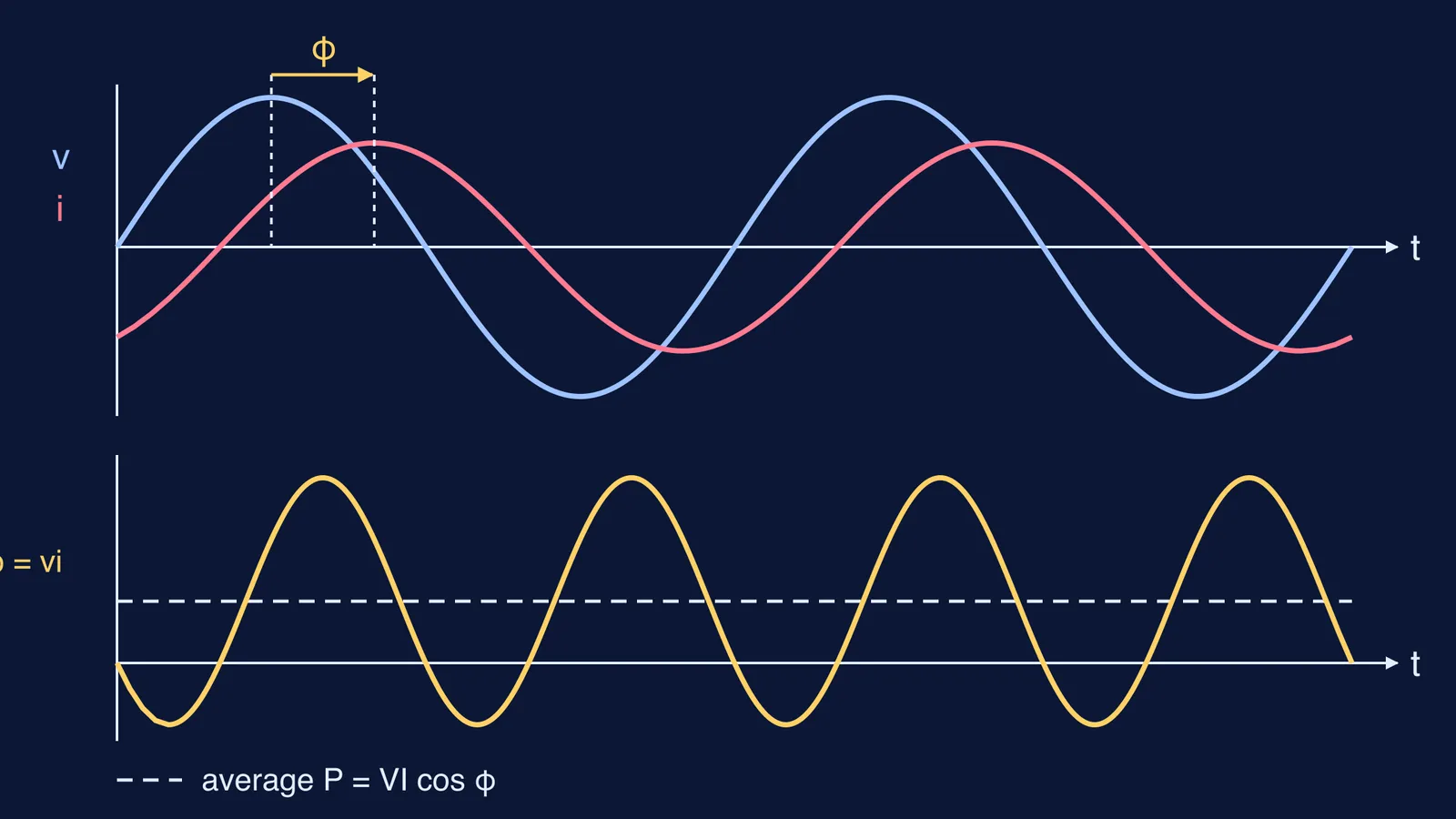
Instantaneous power is p = vi, the product of the two waves at each moment. NCERT expands this as p = (vₘiₘ/2)[cos φ − cos(2ωt + φ)] in the same chapter. The second term swings above and below zero twice per cycle and averages to nothing. Only the steady cos φ term survives.
When v and i are in phase, their product is never negative: the source always pushes energy into the load. Shift the current by φ and there are stretches where v and i have opposite signs. There p is negative and the circuit hands energy back to the source. The bigger φ, the longer those stretches.
At φ = 90° the positive and negative areas are equal. NCERT's Case (ii) says a pure inductor or capacitor then dissipates no power even though a current flows, and calls this a wattless current.
How can you see power factor in a simulation?
Any free graphing tool with sliders will do.
Plot the voltage v = sin x.
Add a slider a from 0 to 90 (degrees) and plot i = sin(x − a·π/180), a current lagging by a.
Plot p = v × i in a third colour.
Plot the line y = 0.5 cos(a·π/180), the average of p.
Set a = 0. The p curve never goes below zero and its average is 0.5.
Drag a to 60. The p curve dips below zero and the average falls to 0.25, though the peaks of v and i did not change.
Drag a to 90. The p curve is symmetric about zero and the average lies on the axis.
For more, the Fermi Simulation Lab has interactive simulations for the ideas that are easier to see than to read.
Worked example: same volts and amps, different power
NCERT Example 7.8 in the AC chapter applies a 283 V peak, 50 Hz source to a series LCR circuit with R = 3 Ω, L = 25.48 mH and C = 796 μF. It finds Z = 5 Ω, φ = −53.1°, an rms current of 40 A, power of 4,800 W and a power factor of 0.6.
The rms voltage there is 283/√2, about 200 V. Keep V = 200 V and I = 40 A fixed, so VI = 8,000 W, and change only the phase:
φ = 0°: cos φ = 1, P = 8,000 W
φ = 30°: cos φ ≈ 0.866, P ≈ 6,928 W
φ = 53.1°: cos φ = 0.6, P = 4,800 W (the NCERT answer; the sign of φ does not change cos φ)
φ = 60°: cos φ = 0.5, P = 4,000 W
φ = 90°: cos φ = 0, P = 0 W
Cross-check: P = I²R = 40² × 3 = 4,800 W, since only the resistor dissipates power. For Z and φ step by step, see our post on deriving LCR impedance and resonance.
Why do power companies care about power factor?
NCERT Example 7.7 explains that to deliver a given power at a given voltage, a small cos φ needs a larger current, and that raises the I²R loss in transmission lines. Its fix is a capacitor of suitable value in parallel, whose leading current cancels the lagging wattless component.
HyperPhysics adds that below a power factor of one, utilities must supply more current for the same power, and an industrial site may be charged a penalty if its power factor is far from 1. The same logic explains why a choke coil is used instead of a resistor in AC circuits.
A quick checklist for JEE and board answers
From the cases in the NCERT chapter:
Unless the circuit is purely resistive, find φ before writing P; in a series circuit, cos φ = R/Z.
Pure L or pure C: power factor 0, average power 0.
At resonance the inductive and capacitive reactances are equal, so φ = 0 and the power factor is 1.
In a series circuit, cross-check every answer with P = I²R.
To practise, try worked problems in the Fermi Problem Library, whose step-by-step solver explains the reasoning rather than printing an answer.