
On this page
Look up at almost any main line in India and you will see a thin wire running above the track. It carries 25,000 volts, and the train underneath turns that into motion. The Ministry of Railways says 99.2% of India's broad-gauge routes are now electrified (The Week, December 2025), so the circuit below runs almost everywhere on the network.
How does an electric train get electricity from the overhead wire?
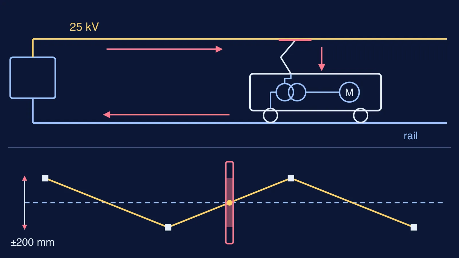
It starts at a traction substation. A training presentation on Indian overhead equipment, hosted by AITD, shows each substation taking power from the 220, 132 or 110 kV grid and feeding 25 kV AC, single phase, to the overhead line (AITD: Standards and Practices, Overhead Electric Equipments).
The wire the train touches is the contact wire. It hangs by thin droppers from a second wire, the catenary, and sits between 4.80 m and 5.80 m above rail level, with a cross-section of 107 mm² (AITD). For why such wires are copper, see why copper is used in electric wires; for how 25 kV is kept off the steel masts, see why electric poles have white cups.
The pantograph is the folding arm on the roof. It is spring-loaded and pushes a contact strip against the underside of the wire; the strip is usually graphite, which conducts and lubricates at the same time (Pantograph, Wikipedia)).
What happens to the 25 kV inside the locomotive?
Motors are not built for 25 kV, so the first stop is the main transformer. In Indian three-phase locomotives it has a 25 kV primary winding and a 1,269 V traction secondary (IRIMEE: Introduction to Electric Locomotive). A transformer needs changing current to work, which is one reason the line is AC; our post on why a transformer does not work on DC explains the physics.
The IRIMEE notes then describe three stages:
A line converter turns the 50 Hz AC from the transformer into DC.
DC link capacitors hold that DC voltage steady.
A drive converter turns the DC back into three-phase AC, at whatever voltage and frequency the motors need at that moment.
The motors are squirrel-cage induction motors. Three motors on each bogie share one converter, and each is rated 2,180 V and 270 A (IRIMEE). A WAP-7 passenger locomotive carries six of them (WAP-7, Wikipedia). Raising the frequency makes the motor's magnetic field spin faster, and the rotor follows it round.
How does the current get back to the substation?
After passing through the transformer's primary winding, the current goes down through the wheels into the steel running rails, which act as the main return conductor to the substation (Open Exam Prep: AC OLE principles; Overhead line, Wikipedia). Rail joints are bridged by bonds, electrical connections between lengths of rail, so the return path stays continuous (AITD).
Neighbouring substations are normally on different phases of the grid, so their wires must never meet. Between them sits a neutral section: a short, insulated, dead stretch of wire, announced to the driver by warning boards, according to the same AITD slides.
Why does the overhead wire zig-zag?
If the wire ran straight down the middle of the track, it would rub one spot on the pantograph strip and soon cut a deep groove into it (Open Exam Prep). So at each support the wire is pulled to alternate sides of the track centre, typically by about 200 to 250 mm (Railway News: OCS guide). Between supports it runs straight, so as the train moves, the contact point slides across the strip and back, spreading the wear evenly (Overhead line, Wikipedia). The same Railway News guide gives a typical carbon strip width of 1,200 to 1,600 mm, much wider than the band the wire sweeps, so the wire stays on it.
Worked example: why use 25,000 volts at all?
Take a WAP-7 at its maximum output of 4,740 kW (WAP-7, Wikipedia). IRIMEE's notes say three-phase locomotives draw power at unity power factor, so P = VI is a fair estimate if we ignore losses on board (IRIMEE).
At 25,000 V: I = 4,740,000 ÷ 25,000 ≈ 190 A.
If the wire ran at the transformer's 1,269 V instead: I = 4,740,000 ÷ 1,269 ≈ 3,735 A.
Heat lost in the wire is I²R. For the same wire, the loss ratio is (25,000 ÷ 1,269)² ≈ 19.7² ≈ 388.
So feeding the wire at 25 kV cuts heating in it about 388 times for the same train. If I²R or turns-ratio problems trip you up, the Fermi Problem Library has worked problems with a step-by-step solver that explains the reasoning rather than printing an answer.
What can you spot on your next train journey?
The arms on each mast that hold the wire, alternating left and right of the track.
The pantograph's flat top strip pressed against the wire.
Short bonds fixed across rail joints.
Warning boards before a neutral section, where the wire is dead.
If AC, transformers and rotating fields are hard to picture, the Fermi Simulation Lab has interactive simulations for ideas that are easier to see than to read.