
On this page
If you are doing a mechanical diploma, you will spend many workshop hours beside CNC machines. Learning to write the program, not just press Cycle Start, is the step from operator to programmer. Here is how a program is built, one worked by hand, and the routes into the job.
A CNC (computer numerical control) machine cuts material by following a program of coordinates and commands. The international standard for that program format is ISO 6983-1, which covers positioning, line motion and contouring control systems; on the shop floor the language is called G-code.
How is a CNC machine programmed?
The Directorate General of Training's Advanced CNC Machining Technician curriculum says it plainly: "The input in this trade is always the drawing." The programmer picks a zero point on the part, works out every edge relative to it, and writes those positions as blocks of code. The curriculum then teaches running programs in various modes and optimising them for idle movement to cut cycle time.
A handful of codes, as defined in the LinuxCNC G-code reference and M-code reference, covers most simple programs:
G0 moves the tool at rapid rate, for positioning rather than cutting.
G1 moves in a straight line at the programmed feed rate, set by F.
G2 cuts a clockwise arc and G3 a counterclockwise one; I and J give the arc centre as an offset from where the arc starts.
G21 sets millimetres, and G90 makes positions absolute, measured from the origin.
M3 starts the spindle clockwise, M5 stops it, and M30 ends the program.
Worked example: how do you program a rounded corner?
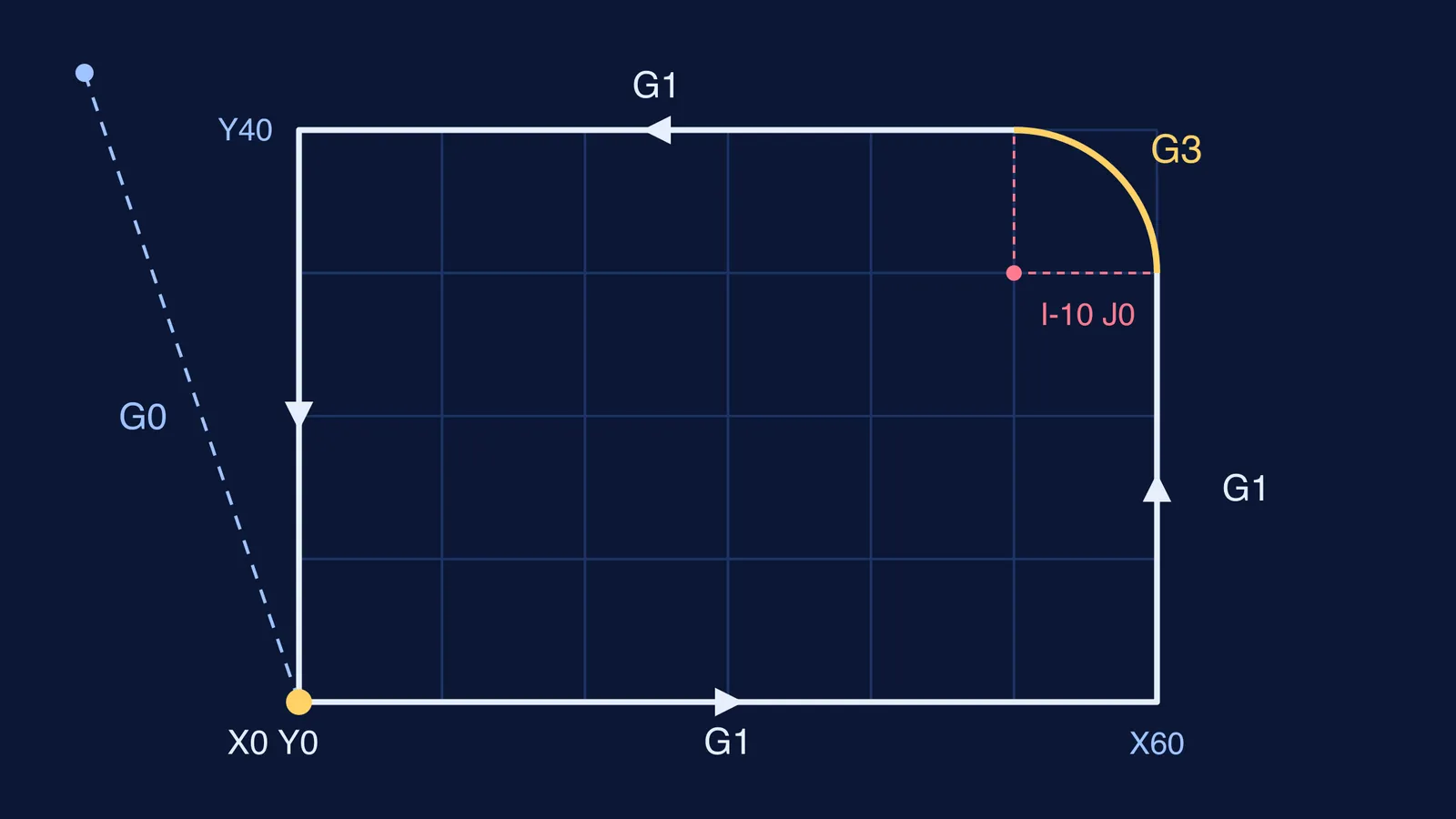
Say the drawing shows a 60 by 40 mm plate with its top-right corner rounded to a 10 mm radius, and you must cut the outline 2 mm deep. With the origin at the bottom-left corner, the program reads:
G21 G90 G17 G94 (millimetres, absolute positions, arcs in the XY plane, feed per minute)
S1200 M3 (spindle on, clockwise)
G0 X0 Y0 Z5 (rapid to 5 mm above the origin)
G1 Z-2 F80 (feed 2 mm down into the material)
G1 X60 F150 (bottom edge)
G1 Y30 (right edge, stopping where the curve begins)
G3 X50 Y40 I-10 J0 (rounded corner, counterclockwise)
G1 X0 (top edge)
G1 Y0 (left edge, back to the start)
G0 Z5 (rapid up, clear of the part)
M5 (spindle off)
M30 (end of program)
Now check line 7 the way a programmer would. The arc starts at (60, 30), and I-10 J0 puts its centre at (50, 30). The end point (50, 40) is also 10 mm from that centre, so the radius matches the drawing. That check is Class 11 coordinate geometry. One caution: this program traces the centre of the tool, and real programs also allow for the cutter's radius.
If circles on a coordinate plane still feel shaky, the Fermi Concept Library has a lesson for every concept in mathematics, so you can close that gap before your CNC theory exam.
Which route into CNC programming suits a diploma student?
There are three main routes, and you can move between them.
ITI trade. DGT's Advanced CNC Machining Technician trade runs for two years: 2,400 hours plus 300 hours of on-the-job training or a group project. It is open after Class 10, sits at NSQF Level 4 and ends in a National Trade Certificate. Its listed job roles include CNC Programmer and Machine Shop Supervisor, and its progression pathways include lateral entry into a diploma. Our guide to choosing ITI or polytechnic after Class 10 compares the two.
Mechanical diploma. The same DGT document accepts a three-year AICTE-recognised mechanical diploma as one qualification for the trade's instructors. Use those years to build the habits above, so you can move from operating machines to programming them.
B.Tech by lateral entry. Clause 6.13 of the AICTE Approval Process Handbook 2024-27 allows lateral entry to the second year of a degree course up to 10% of the approved intake, over and above it, plus unfilled first-year seats. Eligibility and counselling rules vary by state, so check your state's technical education portal. Our automobile diploma to B.Tech routes guide shows how the lateral entry timeline works, and our guide to production and industrial engineering suits you if you would rather plan whole factories.
What should you practise this semester?
A four-week plan to run alongside classes:
Week 1: take one drawing from your workshop and list every dimension and tolerance against a single origin.
Week 2: write its program by hand, then check every arc with coordinate geometry, as in the example above.
Week 3: run it in your institute's simulator and ask your instructor for a supervised dry run.
Week 4: time the cycle, remove wasted rapid moves, and measure the first part.
Keep the program, the simulation result and your measurements in one folder. In an interview, that folder shows what you can do better than a list of machine names.