
On this page
A plug warm at the socket, a switchboard with a brown scorch mark: often the cause is one joint where two metal surfaces no longer press firmly together. Predict where the heat goes before you calculate it.
Where does a circuit heat most when one joint is loose?
Picture a room heater on a 5 m lead, with one loose screw terminal on the live wire. Pick one:
The heater, because it uses the most power.
The long wire, because it has the most length.
The loose joint.
Nowhere new: a bad joint just lets less current through.
If you picked 4, hold that thought: the current barely changes, which is exactly why the joint is dangerous.
Why does a loose wire connection get hot?
Metal surfaces that look flat are rough up close. Current crosses only through small spots of real contact, and squeezing it through them creates constriction resistance. As this summary of electrical contact theory puts it, the real metal-to-metal contact area is small, and more contact force enlarges those spots and lowers the resistance. A loose screw means less force, smaller spots and more resistance.
The joint is in series with the wire and the heater, so one current flows through all three. The power turned into heat is P = I²R, which OpenStax College Physics derives from P = IV and Ohm's law. Same current, so where resistance is packed tightest, heat is packed tightest. It can feed on itself too: a forensic engineer's account describes heat oxidising the joint, which adds resistance.
What did lab tests of loose connections find?
In 1976, W. J. Meese and R. W. Beausoliel at the US National Bureau of Standards (now NIST) loosened connections in 120 V household circuits rated 15 and 20 A, using copper and aluminium wire. Their report, NBSIR 76-1011, found that glowing connections dissipated up to 35 W at 15 A, and up to 5 W at just 0.8 A. Temperatures above 750°F (about 400°C) were measured on the break-off tabs of receptacles, and metal outlet boxes in an insulated test wall passed 450°F (about 230°C).
The finding that matters most: glowing connections did not noticeably affect appliances and did not blow fuses or trip breakers. A fuse responds to too much current, as in a short circuit, where the current soars. A loose joint is too much resistance in one spot.
Worked example: one loose joint in a heater circuit
These are realistic assumptions, not measurements: a 230 V supply, a 23 Ω heater, a 5 m lead with two 1.5 mm² copper conductors, and a 0.15 Ω loose joint, close to the NBS report's figure (35 W at 15 A implies about 0.16 Ω).
Wire resistance. Copper's resistivity is 1.72 × 10⁻⁸ Ω·m, from the OpenStax resistivity table. One conductor: R = ρL/A = 1.72 × 10⁻⁸ × 5 ÷ 1.5 × 10⁻⁶ ≈ 0.057 Ω. Live plus neutral: about 0.115 Ω.
Current. Total resistance is 23 + 0.115 + 0.15 ≈ 23.26 Ω, so I = 230 ÷ 23.26 ≈ 9.89 A. With a tight 0.001 Ω joint it would be 9.95 A, a drop of under 1%, far too small for a breaker to notice.
Power in each part, with I² ≈ 97.7 A².
Heater: 97.7 × 23 ≈ 2,250 W, spread over a large element built to shed it.
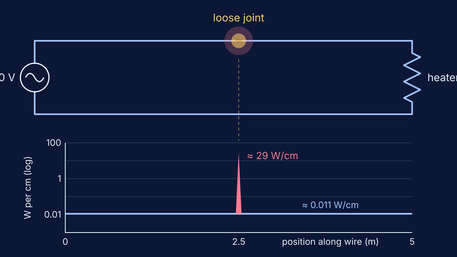
Each 5 m conductor: 97.7 × 0.057 ≈ 5.6 W, about 0.011 W per centimetre.
Loose joint: 97.7 × 0.15 ≈ 14.7 W, in a few millimetres.
So the heater takes the most total power, but the joint is the hottest spot. Released within about 5 mm, its 14.7 W is roughly 29 W per centimetre, around 2,600 times the wire's rate. A tight joint would release about 0.1 W.
How can you test this without touching mains?
Never experiment on a socket or switchboard. Use a circuit simulation instead:
Build a cell, a bulb and wires, with a small resistor where the joint would be.
Predict the current and power in each part, then read them. The current is the same everywhere, because current is not used up in a series circuit.
Raise the joint resistance in steps and plot joint power against it.
Challenge: which joint resistance makes the joint's power largest? Compare it with the rest of the circuit.
The Fermi Simulation Lab has interactive simulations for ideas that are easier to see than to read. If a step in the worked example lost you, the Fermi Problem Library has a step-by-step solver that explains the reasoning rather than printing an answer.
For where the formula came from, read the history of Joule's law of heating, H = I²Rt.