
On this page
You paste a circuit into a chatbot. It replies, "R1 and R2 are in series, so they add to 3 Ω," and gives a tidy number. Often that is right. But if it misreads which resistor joins which point, every line after is neat arithmetic on the wrong circuit. The check needs only a pencil: name every node, give it a potential, redraw, then compare.
How often does AI get circuit problems wrong?
The CircuitReason-1k benchmark, posted in August 2026, tested three commercial chatbots and six open-source multimodal models on 1,000 authentic textbook circuit problems. The highest-scoring system reached 84.8% accuracy. The authors report that performance consistently fell on long-horizon, many-step problems, with persistent failures in "topology-to-target binding": connecting the shape of the circuit to the quantity asked for.
A separate benchmark of printed circuit board schematics, OmniSch, found "inconsistent global connectivity reasoning" in current large multimodal models. Deciding series and parallel is exactly that job.
When are two resistors really in series?
Two resistors are in series only when the same current must flow through both, which means the node between them connects to nothing else.
Two resistors are in parallel only when both of their ends sit on the same two nodes (see our post on resistors connected to the same two nodes).
A plain wire joins its ends into one node at one potential.
Some networks are neither. The NCERT Class 12 chapter on current electricity says of its cube example that the network "is not reducible to a simple series and parallel combinations of resistors" and solves it with symmetry plus Kirchhoff's junction and loop rules. A bridge is the classic network where a series-parallel reading is tempting but wrong.
How do you check an AI's answer with node potentials?
Letter every junction. Points joined only by plain wire share a letter.
Put the input terminal at, say, 10 V and the output at 0 V.
For each "in series" claim, look at the node between the pair. If a third branch touches it, the claim is wrong.
For each "in parallel" claim, check both ends carry the same two letters.
If there is a bridge, test the balance condition before deleting it.
If it is not balanced, write one current equation per unknown node, solve for the potentials, and find the total current. Equivalent resistance is applied voltage divided by that current.
Worked example: a bridge the AI might flatten
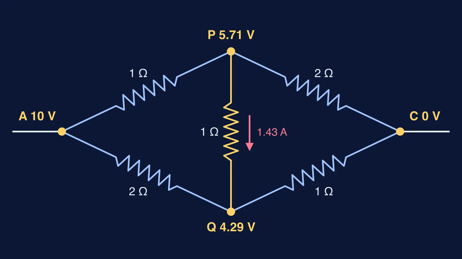
Terminals A and C. Top path: A to P through 1 Ω, P to C through 2 Ω. Bottom path: A to Q through 2 Ω, Q to C through 1 Ω. A 1 Ω resistor joins P and Q.
The shortcut answer: top 1 + 2 = 3 Ω, bottom 3 Ω, two 3 Ω paths in parallel, so 1.5 Ω.
Now check. Node P touches three resistors: A–P, P–C and P–Q. So the top pair is not in series, and the shortcut works only if no current flows through P–Q, which needs a balanced bridge. The NCERT balance condition (Section 3.13) needs the arm ratios on each side to match. Here the top arms are 1 : 2 and the bottom 2 : 1, so it is not balanced.
Set A at 10 V and C at 0 V, and make current in equal current out at each middle node:
At P: (10 − P)/1 = P/2 + (P − Q)/1, which gives 2.5P − Q = 10.
At Q: (10 − Q)/2 = Q/1 + (Q − P)/1, which gives 2.5Q − P = 5.
So P = 40/7 ≈ 5.71 V and Q = 30/7 ≈ 4.29 V. Current leaving A is (10 − 40/7)/1 + (10 − 30/7)/2 = 50/7 A, so the equivalent resistance is 10 ÷ (50/7) = 1.4 Ω, not 1.5 Ω. About 1.43 A flows through the bridge from P to Q.
If an AI gives exactly the "cut bridge" value for an unbalanced bridge, it ignored the middle resistor. A star-delta transformation is another way to cross-check.
What should you type back to the AI?
Do not just ask "are you sure?" (see why AI agrees with a wrong answer). Ask it to show the structure:
"List every node and the resistors that touch it."
"You said these two are in series. Which node lies between them, and what else connects there?"
"Is this bridge balanced? Show the two ratios."
"Take A as 10 V and C as 0 V. Give the potential at every node."
Where its node list differs from yours, the error is in reading the circuit, not the arithmetic.
To practise on more networks, the Fermi Problem Library has worked problems with a step-by-step solver that explains the reasoning rather than printing an answer. If Kirchhoff's rules themselves feel shaky, start with the lesson on them in the Fermi Concept Library.
Next time an AI says "in series", put your finger on the node in between and count the wires.