
On this page
A circuit question shows three resistors in a neat row, end to end, between points A and B. Your eye says series. Then you notice two wires looping over and under the row, and the answer is nothing like the sum. These questions test one skill: seeing which points are electrically the same, whatever the drawing looks like. Here is a five-step labelling method, a worked example you can check, and the common traps.
What makes resistors parallel, exactly?
The definition is about potential, not position on the page. In a parallel configuration, "each resistor has the same potential drop across it," according to OpenStax University Physics, Volume 2.
The same potential drop means the same two end points, electrically. So the working test is: two resistors are in parallel when one end of each sits on node P and the other end of each sits on node Q.
For parallel resistors, 1/R = 1/R1 + 1/R2 + 1/R3 + ..., and OpenStax notes the result is always less than the smallest individual resistance. That gives you a free check on every answer.
Why does a plain wire not change anything?
In circuit problems, connecting wires are treated as having no resistance. OpenStax's chapter on Kirchhoff's rules puts it simply: since the wires have negligible resistance, the voltage stays constant as you cross the wires connecting the components.
That is the whole trick. However long or bent a wire is, every point on it is at one potential, so the whole stretch is one node. You can stretch or shrink it freely, as long as it touches the same resistor ends.
How students reason about circuits is a long-studied problem: Lillian McDermott and Peter Shaffer at the University of Washington investigated student understanding of electric circuits as a research base for laboratory-based instruction (American Journal of Physics, 1992).
How do you label nodes in a tricky circuit?
Mark the two terminals, A and B, where the equivalent resistance is asked.
Start at A. Trace every wire you can reach without passing through a resistor. Every point you reach gets the label A.
Do the same from B, then give any remaining wire region its own letter (C, D...).
Write each resistor's two end labels beside it, for example "6 ohm: A to B".
Group them. Same pair of labels means parallel. Both ends with the same label means the resistor is shorted and carries no current. Two resistors meeting at a node that touches nothing else are in series. Then redraw: A as a top rail, B as a bottom rail, each resistor hanging between its labels.
Worked example: three resistors that look in series
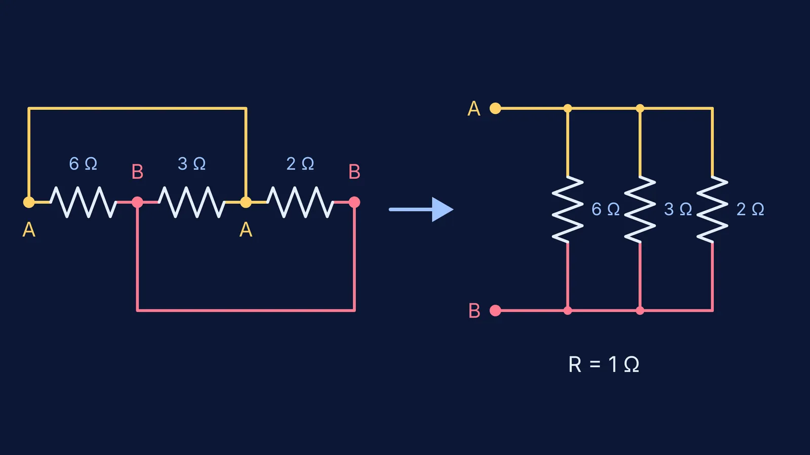
This is the circuit in the image at the top. Resistors of 6 ohm, 3 ohm and 2 ohm sit in a row: A, then 6 ohm, then point X, then 3 ohm, then point Y, then 2 ohm, then B. One wire runs from A over the top to Y. Another runs from X under the bottom to B.
Label it:
Y is joined to A by plain wire, so Y is A.
X is joined to B by plain wire, so X is B.
The 6 ohm resistor runs from A to X, which is A to B.
The 3 ohm resistor runs from X to Y, which is B to A.
The 2 ohm resistor runs from Y to B, which is A to B.
All three share the same two nodes, so all three are in parallel. Then 1/R = 1/6 + 2/6 + 3/6 = 1, so R = 1 ohm. Treated as series, you would have written 11 ohm.
Check: put 6 V across A and B. Each resistor has the full 6 V across it, so the currents are 1 A, 2 A and 3 A, a total of 6 A. Then 6 V divided by 6 A gives 1 ohm, which is below the smallest resistor, 2 ohm, as the OpenStax rule says it must be.
If your answer comes out wrong and you cannot see why, the Fermi Problem Library has worked problems with a step-by-step solver that explains the reasoning rather than printing an answer, so you can compare its node-by-node steps with yours.
What traps should you watch for?
Crossing wires. In most textbook diagrams, wires that cross without a dot are not joined. Check your paper's convention.
Shorted resistors. If both ends land on the same label, drop the resistor; here is why no current flows through a short-circuited resistor.
False series. Two resistors sharing a node are in series only if nothing else leaves that node.
Bridges. If a resistor ends up between two nodes that are neither A nor B, series and parallel alone may not finish the job. Try combination of resistors: series, parallel and symmetry shortcuts, or assign voltages with the node potential method.
If potential difference still feels shaky, the Fermi Concept Library has a lesson for every concept in physics.
Next time a circuit looks strange: label, redraw, then calculate.