

On this page
If you have ever stared at a complex circuit diagram in a physics exam, you have likely seen this trick: a maze of zig-zag lines with one perfectly smooth, plain wire drawn across a resistor. When you calculate the total current, that bypassed resistor drops out entirely. It is a common source of confusion for many students learning about electric circuits for the first time.
But why does a short-circuited resistor draw exactly zero current, rather than just less current? The answer comes down to voltage drops and the rules of parallel circuits.
Why does current follow the path of least resistance?
When electricity reaches a junction, it divides into all available paths. The amount of current flowing through each path is inversely proportional to its resistance.
When a standard resistor is placed in parallel with a plain wire, the plain wire acts as a short circuit with near-zero resistance. The equivalent resistance of a parallel combination with a zero-ohm branch becomes zero. Because the wire's resistance is so exceptionally low, it becomes the ultimate "path of least resistance," and all the current flows through it.
Why does the voltage drop become zero?
While thinking about current is helpful, looking at voltage gives a more rigorous answer. Voltage is the "push" (potential difference) that moves electrons through a component.
As explained by The Physics Classroom, every branch in a parallel circuit must share the exact same voltage drop.
An ideal wire has zero resistance. By Ohm's law, the voltage drop across a zero-ohm wire is always 0 V.
Because the resistor is wired in parallel with this plain wire, its voltage drop is also forced to 0 V.
With zero potential difference across its terminals, there is no electrical pressure to push charges through the resistor. Therefore, the current through the bypassed resistor is exactly 0 A.
What happens to the math when a resistor is shorted?
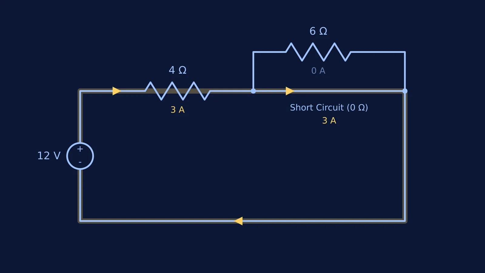
To see the impact numerically (using Ohm's law, as detailed by The Physics Classroom), imagine a 12 V battery connected to a 4 Ω resistor in series, followed by a 6 Ω resistor.
Without a short circuit:
The total resistance is 4 Ω + 6 Ω = 10 Ω.
The total current is 12 V / 10 Ω = 1.2 A.
Both resistors share this current, getting warm as they dissipate power.
Now, imagine someone connects a plain copper wire across the two terminals of the 6 Ω resistor.
The plain wire is in parallel with the 6 Ω resistor. Their combined equivalent resistance is zero.
The new total resistance of the circuit is just the 4 Ω series resistor plus the 0 Ω short, which equals 4 Ω.
The new total current surges to 12 V / 4 Ω = 3 A.
Because the shorted 6 Ω resistor is bypassed, it stays cold, drawing 0 A. Meanwhile, the battery now has to push 3 A through the remaining 4 Ω resistor, generating far more heat. This sudden surge in current is why physical short circuits can be dangerous, often causing wires to melt or batteries to overheat if there is no safety fuse.
How do you spot hidden shorts in exam diagrams?
Exam setters love to hide short circuits in plain sight. They might draw a square of resistors, add a diagonal wire, and ask for the equivalent resistance.
If you are stuck on a maze of components, the Fermi Problem Library has a step-by-step solver that explains the reasoning for which resistors to cross out. But you can spot these traps yourself using this three-step framework:
Trace the nodes: Pick up a coloured pen and trace the plain wire. A "node" is any continuous stretch of wire without a component.
Check the terminals: Look at where each resistor connects. If both ends of a resistor touch the same coloured wire (the same node), it is short-circuited.
Cross it out: Because both ends are at the same potential, no current will flow through it. You can cross the resistor out and redraw the circuit without it.
This is the foundation of the node potential method, where you assign 0 V to the negative terminal and step through the circuit. It is a powerful way to simplify a combination of resistors, or even an infinite ladder of resistors.
A short circuit simply means the two ends of a component have been connected by a free ride. Find the free ride, cross out the bypassed resistor, and the rest of the problem will fall into place.


