
On this page
Ask who invented the screw gauge and you get two answers. The idea of measuring a tiny distance by turning a fine screw came from William Gascoigne, a young astronomer near Leeds, in the 1630s. The handheld tool you clamp on a wire in the lab came about two centuries later.
Who invented the micrometer screw gauge?
William Gascoigne was born around 1612 in Middleton, Leeds, and died on 2 July 1644 at the Battle of Marston Moor (William Gascoigne, Wikipedia)). He was about 32 years old (Linda Hall Library, Scientist of the Day).
His micrometer had two pointers whose gap was set by a screw (Wikipedia)). The 1911 Encyclopaedia Britannica calls him "the first inventor of the micrometer" and notes that Flamsteed published Gascoigne's measurements with it from 1638 to 1643 (1911 Britannica, Micrometer).
The workshop version came much later. J. Palmer's micrometer was patented in 1848 as the "System Palmer", and Brown and Sharpe saw it at the 1867 Paris International Exposition and took it to America (Mitutoyo, micrometer history). Mitutoyo is a manufacturer, so treat this as industry history.
How did Gascoigne's telescope micrometer work?
It started with an accident. In the late 1630s, a thread from a spider's web got caught exactly where the two lenses of his telescope came to a focus, and Gascoigne saw it bright and sharp in the field of view (Wikipedia)).
So he put two pointers there, in front of the eyepiece (Linda Hall Library). At zero their edges touched. Turning one screw moved them apart symmetrically, in opposite directions, until they touched opposite edges of the Moon. An index on the screw read fractions of a turn on a dial of 100 equal parts (1911 Britannica). Turns plus the dial reading gave the gap, and from that the Moon's angular diameter.
Later, the French astronomers Auzout and Picard used silk fibres or silver wires, with one kept fixed and the other moved by the screw (1911 Britannica). That is the layout you know: a stud that stays put and a screw that moves.
His credit had to be defended after his death. In 1667 Richard Towneley wrote to the Royal Society to defend Gascoigne's originality and priority (Linda Hall Library). The Society's journal printed "A description of an instrument for dividing a foot into many thousand parts, and thereby measuring the diameters of planets to great exactness" (Philosophical Transactions, vol. 2, no. 29), with Robert Hooke's engraving of the micrometer.
Why does a screw gauge measure so finely?
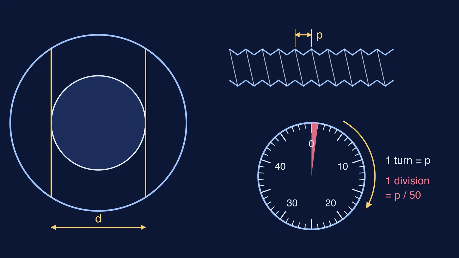
One full turn moves a screw forward by one pitch, and NCERT's Class 11 lab manual says this pitch is usually 1 mm or 0.5 mm (NCERT Laboratory Manual, Experiment 2).
The least count is the pitch divided by the number of divisions on the circular scale. With a 0.5 mm pitch and 50 divisions, it is 0.5 mm ÷ 50 = 0.01 mm. NCERT puts Vernier callipers at about 0.1 mm and screw gauges at 0.01 mm or 0.005 mm, which is why you use a screw gauge on a wire.
The idea is Gascoigne's: a whole turn moves the screw by only one pitch, and a divided dial reads the fraction of a turn. If the two scales still confuse you, read our guide to Vernier and screw gauge readings, or the story of Pierre Vernier's 1631 scale. If an idea is easier to see than to read, the Fermi Simulation Lab has interactive simulations you can try.
How do you read a screw gauge with zero error?
Take a gauge with a 0.5 mm pitch and 50 circular divisions, so the least count is 0.01 mm. NCERT's rule is: total reading = linear scale reading + circular scale reading × least count (NCERT Laboratory Manual).
Close the gauge with the ratchet. Say the circular scale reads 3: the zero error is +3 × 0.01 = +0.03 mm.
Grip the wire, using the ratchet until it clicks. Say the linear scale shows 1.5 mm and division 37 lines up with the reference line.
Observed reading = 1.5 + 37 × 0.01 = 1.87 mm.
Corrected reading = observed reading − zero error = 1.87 − 0.03 = 1.84 mm.
Turn the wire through 90°, measure again at several places and take the mean, as NCERT asks.
Now suppose the closed gauge read 46, so its zero had gone 4 divisions past the reference line. The zero error is −4 × 0.01 = −0.04 mm, and the corrected reading is 1.87 − (−0.04) = 1.91 mm. Either way, NCERT subtracts the zero error with its sign.
When you practise questions like these, the Fermi Problem Library has a step-by-step solver that explains the reasoning, so you can find the step where a sign flipped. To see how a small reading error grows in a final answer, read our post on error propagation in measurement.
Next time you clamp a wire in the lab, count the turns, as Gascoigne did with the Moon.