On this page
If you search for who invented the vernier caliper, you will encounter two names separated by more than two centuries: French mathematician Pierre Vernier and American toolmaker Joseph R. Brown.
Pierre Vernier was born on 19 August 1584 in Ornans, France, as recorded in his Encyclopaedia Britannica biography. Educated in mathematics and science by his father Jean Vernier, Pierre spent much of his career working as a military engineer and treasury director for the Spanish Habsburg administration. In 1631, he published a landmark treatise in Brussels titled *La Construction, l'usage, et les propriétés du quadrant nouveau de mathématiques*, cited by the MacTutor History of Mathematics Archive. In this work, Vernier described an auxiliary scale that slid alongside a primary scale to measure fractions of a division without visual guesswork.
Vernier's original instrument was not a handheld pocket caliper, but an astronomical quadrant designed to measure the angular elevation of stars. Two centuries later, in 1851, American toolmaker Joseph R. Brown applied Vernier's sliding scale to a handheld jawed caliper that read linear lengths down to 0.001 inches, as documented in Joseph Wickham Roe's history of English and American Tool Builders. While Brown built the modern workshop tool, the optical principle that makes every caliper work belongs entirely to Pierre Vernier.
Why was Vernier's scale better than the nonius?
Before 1631, navigators and astronomers measured fractions of a degree using the nonius, invented in 1542 by Portuguese mathematician Pedro Nunes. Nunes inscribed 45 concentric circular arcs on an astrolabe or quadrant, dividing the outermost into 90 parts and the innermost into 46. An observer noted which arc the sighting index crossed, then calculated fractional angles through proportions.
In practice, engraving 45 accurate concentric arcs was nearly impossible for Renaissance craftsmen. Tycho Brahe turned to transversal diagonal lines, but these required enormous instruments to keep marks legible.
Vernier replaced 45 scales with a single sliding arc. On his 1631 quadrant, the main scale was marked in half-degrees (30 minutes of arc, or 30′). As detailed in MacTutor's record of Pierre Vernier, he attached an auxiliary sector spanning 31 half-degrees (930′), divided into 30 equal parts. Each auxiliary division measured 31′, creating a 1′ difference against the main scale:
1 main scale division = 30′
1 vernier division = 31′
Difference = 1′
An observer only had to find which vernier mark aligned with a main scale mark to read angles to one minute of arc. The device was long called a "nonius," until French astronomer Jérôme Lalande clarified the history in his 1771 edition of Astronomie, firmly establishing the name "vernier."
How does Pierre Vernier's sliding scale work?
Vernier's invention relies on an optical principle: the human eye struggles to estimate fractional spacing between markings, but detects collinear alignment between two meeting lines with remarkable sensitivity.
In laboratory physics courses documented by OpenStax College Physics, calipers use a "direct vernier," where n divisions of the sliding scale cover the exact length of n − 1 divisions of the main scale. Because n divisions occupy the span of n − 1 main divisions, each vernier division is slightly smaller than a main scale division by the Least Count (LC), also called the vernier constant:
Length of 1 Main Scale Division = 1 MSD
Length of n Vernier Scale Divisions = (n − 1) MSD
1 Vernier Scale Division (1 VSD) = (n − 1) / n MSD
Least Count = 1 MSD − 1 VSD = 1 MSD / n
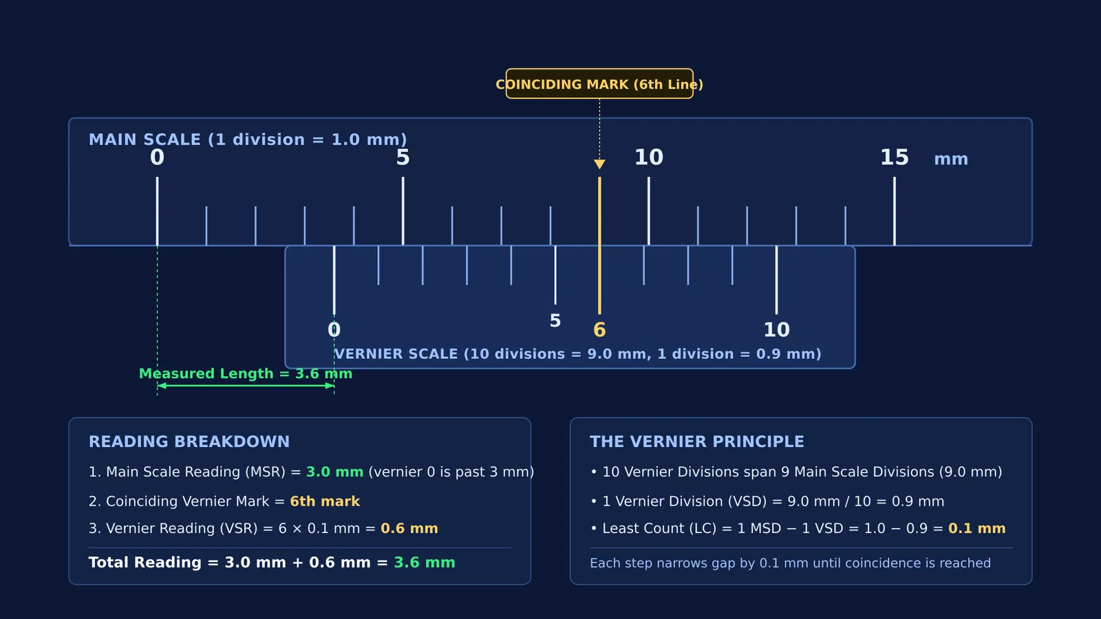
On a standard school caliper, 1 MSD is 1 mm, and 10 vernier divisions span 9 mm:
1 VSD = 9 mm / 10 = 0.9 mm
Least Count = 1 mm − 0.9 mm = 0.1 mm (or 0.01 cm)
When the sliding jaw opens, the vernier zero shifts. The surplus length beyond the last main scale mark corresponds to the specific vernier line that aligns with a main scale line. If the 4th line aligns, the surplus is 4 × 0.1 mm = 0.4 mm.
How do you calculate least count and zero error?
In school practicals outlined by the NCERT Science Laboratory Manual, reading a caliper requires calculating the least count and adjusting for zero error.
Calculating least count:
10-division caliper: 10 VSD = 9 mm → LC = 1 mm / 10 = 0.1 mm = 0.01 cm.
50-division caliper: 50 VSD = 49 mm → LC = 1 mm / 50 = 0.02 mm = 0.002 cm.
Correcting zero error:
When closing the jaws:
No error: Zeroes on both scales coincide.
Positive zero error: The vernier zero sits to the right of the main zero. If the 3rd vernier mark aligns on a 0.1 mm caliper, error is +0.3 mm (+0.03 cm). Corrected Reading = Observed Reading − (+0.03 cm).
Negative zero error: The vernier zero sits to the left of the main zero. If the 7th mark aligns on a 10-division scale, error is −(10 − 7) × 0.1 mm = −0.3 mm (−0.03 cm). Corrected Reading = Observed Reading − (−0.03 cm) = Observed Reading + 0.03 cm.
Handling these offsets links directly to error propagation and combining experimental errors, as well as reading a vernier calliper and screw gauge. This precision mindset matches the historical drive seen in Henry Maudslay's precision screw-cutting lathe.
What does Pierre Vernier's invention mean for students today?
Nearly four centuries later, Pierre Vernier's sliding scale remains the first precision instrument taught in Class 11 physics. It proves that measurement gains come from clever geometry that complements human sight.
When preparing for lab exams, seeing how vernier lines shift is essential. The Fermi Simulation Lab provides interactive simulations for ideas that are easier to see than to read, letting students test scale alignments virtually.
For practicing exam numericals, the Fermi Problem Library features worked problems with a step-by-step solver that explains the reasoning rather than printing an answer. To understand how measurement errors connect to broader mechanics, the Fermi Concept Library covers every concept in physics, chemistry, biology, mathematics and computing, each with its own lesson and its place in the map.