
On this page
Every time you draw a phasor diagram for a series LCR circuit, you are using a method that Charles Proteus Steinmetz set out in the 1890s. In the preface to his textbook Theory and Calculation of Alternating Current Phenomena, Steinmetz called the book "an expansion and extension of my paper on the application of complex imaginary quantities to electrical engineering, read before the International Electrical Congress at Chicago, 1893" (first-edition preface, reprinted in the 1916 edition).
Who was Charles Steinmetz?
Steinmetz was born on 9 April 1865 in Breslau, which is now Wrocław in Poland (IEEE Engineering and Technology History Wiki). At 24 he left Germany and came to the United States "practically penniless and knowing almost no English". His first paper for the American Institute of Electrical Engineers, in 1892, was "On the Law of Hysteresis". In 1893 General Electric moved him to Schenectady, New York, as chief consulting engineer, a role he held until his death.
What problem did complex numbers solve in AC circuits?
In an AC circuit every voltage and current is a sine wave, but the waves are out of step. The current in a resistor is in phase with the voltage, while the current in a pure inductor lags the voltage by a quarter cycle (NCERT Class 12 Physics, Chapter 7: Alternating Current). Adding such waves by trigonometry is slow and error-prone.
Steinmetz's fix was to write each sine wave as a complex number, a + jb, whose size is the wave's amplitude and whose angle is its phase. In his 1916 edition he put the result in one line: "the combination of sine waves is reduced to the elementary algebra of complex quantities" (Steinmetz, 1916, Internet Archive). In the same book, Z = r + jx is "the expression of the impedance of the circuit in complex quantities", where r is resistance and x is reactance. His first-edition preface says he "used only common algebra and trigonometry, practically excluding calculus" in most of the book.
How is the Class 12 phasor the same idea?
NCERT defines it directly: "A phasor is a vector which rotates about the origin with angular speed ω" (NCERT Class 12 Physics, Chapter 7).
That arrow is Steinmetz's complex number drawn on the complex plane. Adding phasors head to tail is adding complex numbers. Multiplying complex numbers adds their angles and multiplies their lengths, and j has length 1 and angle 90 degrees, so multiplying by j turns a phasor by 90 degrees. NCERT's series LCR results come from one complex number, Z = R + j(XL − XC): Z = √(R² + (XC − XL)²) is its modulus, and tan φ = (XC − XL)/R gives its angle with the sign flipped, because NCERT's φ is the phase of the current relative to the voltage.
Worked example: a series LCR circuit with complex numbers
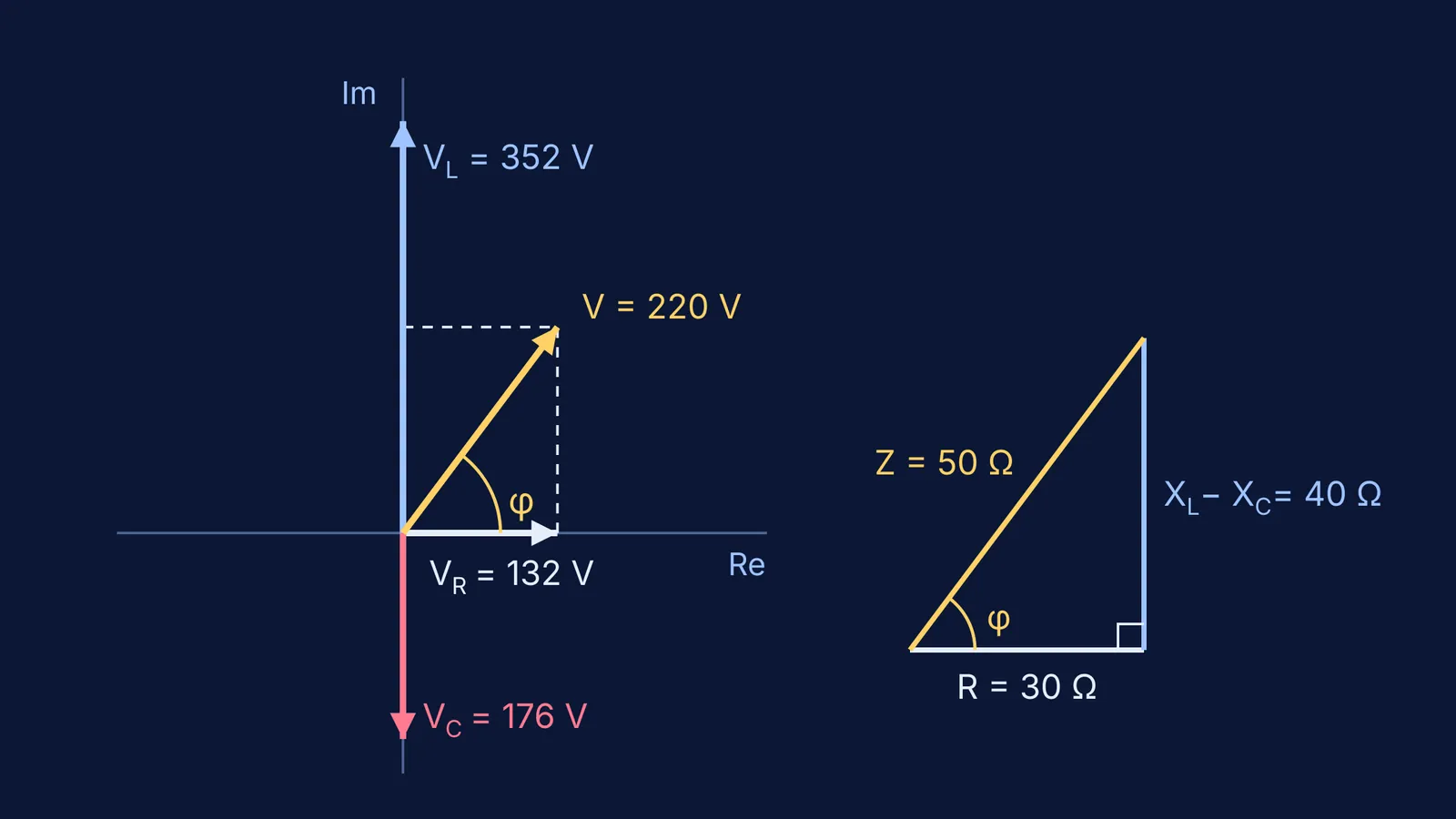
A 220 V (rms) AC supply drives a series circuit with R = 30 Ω, XL = 80 Ω and XC = 40 Ω.
Write the impedance as one complex number: Z = 30 + j80 − j40 = 30 + j40 Ω.
Its size is |Z| = √(30² + 40²) = 50 Ω. Its angle is tan φ = 40/30, so φ ≈ 53.1°. XL is bigger than XC, so the circuit is inductive and the current lags the voltage.
Current: I = 220/50 = 4.4 A (rms). Take the current along the real axis.
Voltages: VR = 4.4 × 30 = 132 V, VL = j(4.4 × 80) = j352 V, VC = −j(4.4 × 40) = −j176 V.
Check: 132 + j352 − j176 = 132 + j176, and √(132² + 176²) = 220 V. The supply voltage comes back.
Power: cos φ = 30/50 = 0.6, so P = 220 × 4.4 × 0.6 = 580.8 W, the same as I²R = 4.4² × 30.
Notice that the three voltmeter readings add to 660 V, far more than the 220 V supply. That is not an error: VL and VC point in opposite directions, which is why the voltage across an inductor can exceed the supply.
If you got a different phase angle, check the sign of XL − XC first. The Fermi Problem Library has worked problems with a step-by-step solver that explains the reasoning rather than printing an answer, so you can find the line where your method went wrong.
How should you practise phasors for board exams?
Draw the current phasor first, along the real axis.
Write R as R, an inductor as +jXL and a capacitor as −jXC.
Add the complex numbers, then take the modulus and the angle.
Check that the element voltages add back to the supply as complex numbers, not as plain numbers.
Know NCERT's limit: a phasor diagram gives only the steady-state solution and says nothing about the initial conditions.
The Fermi Simulation Lab has interactive simulations for ideas that are easier to see than to read, and our series LCR resonance simulation guide shows what happens when XL equals XC.
Next time you write j, you are using Steinmetz's shortcut from 1893.