

On this page
When students connect a series LCR circuit in a physics laboratory, multimeter readings across the inductor often trigger disbelief. As analyzed in OpenStax University Physics Volume 2, an AC source might supply 20 V root-mean-square (RMS) across the entire circuit, yet a voltmeter across the inductor can record 100 V, 200 V, or even more at resonance.
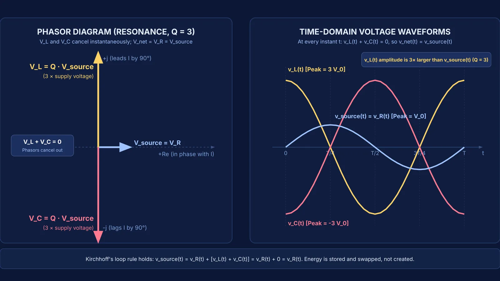
At first glance, this looks like a violation of energy conservation: a passive component appears to deliver several times the total supply voltage. However, the circuit is not generating free energy. In an alternating current circuit, voltages are sinusoidal functions of time. The inductor voltage leads the circuit current by a phase angle of 90° (π/2 rad), while the capacitor voltage lags the current by 90°. At resonance, inductive reactance X_L = ω₀ L equals capacitive reactance X_C = 1/(ω₀ C), placing the two component voltages exactly 180° out of phase with each other.
Why is voltage across the inductor greater than supply voltage in LCR?
The apparent paradox arises because an AC voltmeter does not measure instantaneous potential differences. It reports root-mean-square (RMS) amplitude, which is a scalar magnitude that strips away all phase information. In direct current (DC) circuits, Kirchhoff's loop rule allows you to add voltage drops with ordinary arithmetic. But in alternating current (AC) circuits, as detailed in OpenStax University Physics Volume 2, Kirchhoff's loop rule applies strictly to instantaneous voltages: v_source(t) = v_R(t) + v_L(t) + v_C(t).
Because v_L(t) and v_C(t) are 180° out of phase, when the inductor voltage reaches its positive crest, the capacitor voltage sits at its negative trough. At every single microsecond during resonance, v_L(t) + v_C(t) = 0. The instantaneous voltage drops across the reactive components completely cancel each other out across the series loop. For hard-to-picture ideas that are easier to see than to read, the Fermi Simulation Lab offers interactive simulations where you can trace phasor rotations alongside time-domain sinusoidal curves.
Why don't the RMS voltages across L, C, and R add up to the source?
Because the reactive voltages oppose each other, the net RMS source voltage is given by the phasor formula V_source = √(V_R² + (V_L − V_C)²), as explained in AC circuits for JEE: phasors, impedance and resonance explained and HyperPhysics. When V_L = V_C, the reactive term vanishes entirely, leaving V_source = V_R.
Adding RMS voltages algebraically assumes that all three components peak at the exact same instant, which never occurs in reactive circuits. You can read more about how heat dissipation relates to effective amplitudes in RMS values and power in AC circuits.
How does the quality factor drive voltage magnification?
At resonance, the net reactive impedance cancels to zero, leaving the total circuit impedance at its absolute minimum: Z = R. The current amplitude through the entire series loop is limited solely by the resistance: I_rms = V_source / R.
According to HyperPhysics, the RMS voltage measured across the inductor is V_L = I_rms × X_L = (V_source / R) × (ω₀ L) = V_source × (ω₀ L / R). The dimensionless ratio Q = ω₀ L / R = (1/R) √(L/C) is the quality factor of the circuit. Therefore:
V_L = Q × V_source
V_C = Q × V_source
As recorded in Chapter 7 of the NCERT Class 12 Physics textbook, the quality factor measures the sharpness of resonance and acts as a voltage magnification factor. When circuit resistance is small, Q easily exceeds 1. In radio tuning circuits, Q often ranges from 50 to 200, meaning a faint 10 μV antenna signal can produce 1 mV to 2 mV across the tuning coil. Energy is not created; it is cyclically swapped between the magnetic field of the inductor and the electric field of the capacitor, while the source only replenishes the energy dissipated as heat in resistor R. For a deeper look at tuning bandwidth, explore LCR resonance: quality factor, bandwidth and power factor.
Can an inductor voltage reach 200 V on a 20 V AC supply?
Following the analytical principles in NCERT Class 12 Physics, consider a classic resonance problem: A series LCR circuit is connected to an AC source of V_rms = 20 V. The circuit components have resistance R = 10 Ω, inductance L = 100 mH (0.1 H), and capacitance C = 10 μF (10⁻⁵ F).
Find the resonant angular frequency:
ω₀ = 1 / √(L C) = 1 / √(0.1 × 10⁻⁵) = 1 / √(10⁻⁶) = 1000 rad/s.
Calculate the inductive and capacitive reactances:
X_L = ω₀ L = 1000 × 0.1 = 100 Ω. X_C = 1 / (ω₀ C) = 1 / (1000 × 10⁻⁵) = 100 Ω.
Calculate the quality factor:
Q = X_L / R = 100 / 10 = 10.
Calculate the current and component voltages:
At resonance, Z = R = 10 Ω. I_rms = V_rms / R = 20 / 10 = 2 A. V_R = I_rms × R = 2 × 10 = 20 V. V_L = I_rms × X_L = 2 × 100 = 200 V. V_C = I_rms × X_C = 2 × 100 = 200 V.
The voltmeter across the inductor displays 200 V, which is exactly Q = 10 times the 20 V source. Yet if you place the meter leads across the series LC combination, the reading is V_LC = |V_L − V_C| = 0 V. The net voltage across the entire circuit is √(20² + (200 − 200)²) = 20 V, matching the supply.
How should you evaluate series LCR resonance questions?
When solving AC circuit questions in CBSE board exams or JEE Main, as framed in the NCERT Class 12 Physics curriculum, keep this verification sequence in mind:
Check the frequency: Confirm whether the driving frequency ω equals 1/√(LC). If ω = ω₀, the circuit is purely resistive, the phase constant is 0°, and the power factor is 1.0.
Use phasors, not scalars: Never add RMS voltages directly. Always combine them as vectors using V_source = √(V_R² + (V_L − V_C)²).
Relate reactive voltages to Q: Use V_L = Q × V_source and V_C = Q × V_source at resonance. If Q > 1, expect individual reactive voltages to exceed the line voltage.
Inspect energy flow: Remember that the inductor and capacitor store reactive energy without consuming net power over a complete cycle. Net active power is dissipated only in the resistor: P_avg = I_rms² × R.
To work through multi-step circuit analysis, the Fermi Problem Library has worked problems with a step-by-step solver that explains the reasoning rather than printing an answer.


