
On this page
A rheostat on a lab bench has three terminals: one at each end of the coil and one on the sliding contact. Which ones you wire up decides whether it trims the current or sets any voltage from zero to the full supply. Here are both connections with real numbers and the common mistakes.
What is the difference between a rheostat and a potential divider?
A lab rheostat is a coil of resistance wire along an insulating tube, with a slider that touches the coil at any point. Used with two terminals, "a rheostat is a two-terminal variable resistor that usually adjusts current, rather than voltage," and it "is connected in series with the load", according to RS Components' rheostat guide.
Used with all three terminals, the same coil becomes a potential divider, a circuit that "may be used to supply a variable voltage to an external circuit", as the LibreTexts physics text on potential dividers/04:_Batteries_Resistors_and_Ohm's_Law/4.09:_Potential_Divider) puts it.
How do you use a rheostat as a current limiter?
Connect one fixed end of the coil and the slider terminal. Leave the other fixed end empty.
Put the rheostat in series with the battery, the key, the ammeter and the load.
Before you close the key, slide the contact so the whole coil is in the circuit (maximum resistance).
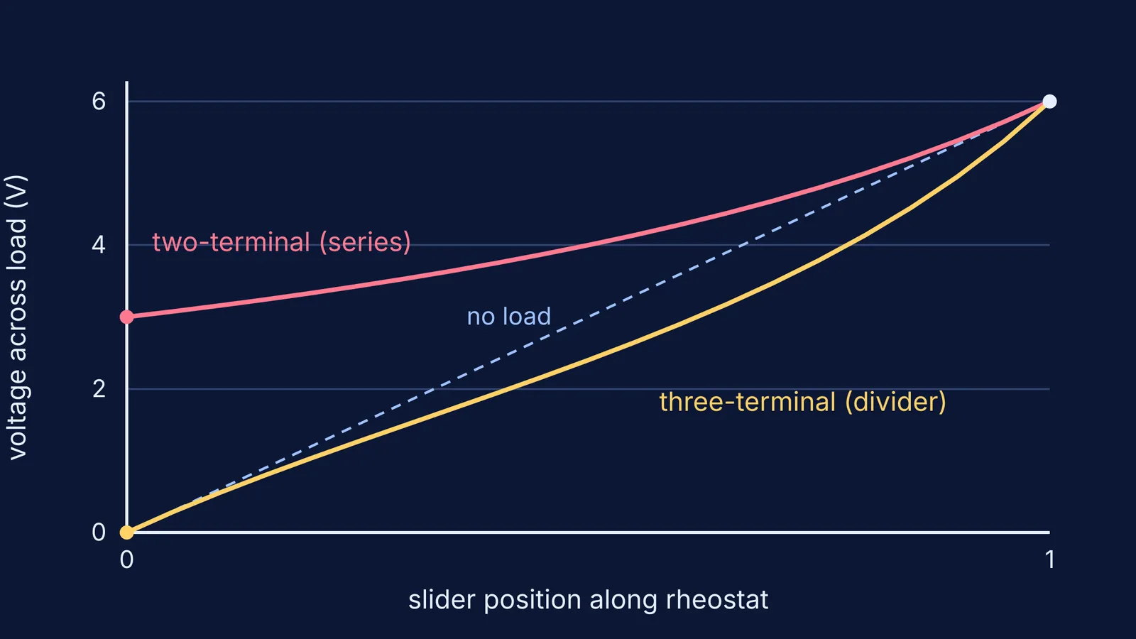
Worked example: a 6 V supply, a 50 Ω rheostat and a 50 Ω load. The current is I = 6 / (50 + R), where R is the part of the coil in use. With the whole coil in, I = 6/100 = 0.06 A and the load gets 3 V. With the slider at the other end, R = 0, I = 0.12 A and the load gets 6 V. However far you slide, the load voltage stays between 3 V and 6 V; it never reaches zero.
Which connection gives zero to full voltage?
The three-terminal connection does:
Connect the battery and key across the two fixed ends of the coil.
Connect the load between the slider and one fixed end, called the zero end.
Start with the slider at the zero end. The load voltage is then 0 V. Slide towards the other end and it rises to the full 6 V.
The voltage does not rise in a straight line once the load draws current. With the slider halfway, the lower 25 Ω of coil is in parallel with the 50 Ω load, which makes 16.7 Ω. That sits in series with the upper 25 Ω, so the load gets 6 × 16.7 / 41.7 = 2.4 V, not 3 V. The graph at the top of this post plots both connections for these values.
The CBSE Physics curriculum for 2025-26 lists "To determine resistivity of two / three wires by plotting a graph for potential difference versus current" as a Class 12 experiment. A divider spreads your readings across the whole range, which makes a better graph; see our guide to plotting physics practical graphs.
What are the common rheostat wiring mistakes?
Using both fixed ends and no slider. The whole coil is always in the circuit, so moving the slider changes nothing.
Putting the supply between the slider and one end. Slide to that end and the battery is short-circuited.
Switching on at the wrong end. In series, start at maximum resistance. In a divider, start at the zero end.
Ignoring the current rating. In a divider, the short stretch of coil between the slider and the supply end carries the whole supply current. In our example with the slider 90% of the way along, that 5 Ω stretch carries about 0.21 A. Check the rated current printed on the rheostat.
Leaving a divider switched on between readings. The coil drains 6/50 = 0.12 A from the battery even with no load attached. Open the key while you write.
Mixing up the meters. Ammeter in series, voltmeter across the load; see how to connect an ammeter and a voltmeter.
Spotting these is on the syllabus: a CBSE Class 12 activity asks students to find components of a "battery, resistor/rheostat, key, ammeter and voltmeter" circuit that "are not connected in proper order" and correct them.
How do you check the circuit before switching on?
Count the rheostat wires: two for a current limiter, three for a divider.
In a divider, trace the battery to both fixed ends, never to the slider.
Put the slider at maximum resistance (series) or at the zero end (divider).
Keep the key open until the teacher has seen the circuit.
If the examiner asks why you used a divider, one sentence is enough: "The divider lets me set the voltage from zero to the full supply, so my graph covers the whole range."
If a loaded divider gives you a number you did not expect, like the 2.4 V above, the Fermi Problem Library has worked problems with a step-by-step solver that explains the reasoning rather than printing an answer. For ideas easier to see than read, try the Fermi Simulation Lab.