

On this page
Practical exams and many circuit questions in Class 10, Class 12 and JEE Main assume you know where the two meters go. This post gives you the rule, the reason behind it and one worked circuit.
How do you connect an ammeter and a voltmeter in a circuit?
An ammeter is connected in series with the component whose current you want, because objects in series have the same current passing through them, as OpenStax University Physics, section 10.4 puts it.
A voltmeter is connected in parallel across the component, because objects in parallel experience the same potential difference (OpenStax University Physics, section 10.4).
Each meter has to measure without disturbing the circuit, and that decides its resistance:
An ammeter sits in the current's path, so it needs a very low resistance; the same OpenStax section says a fraction of a milliohm.
A voltmeter sits beside the component, so it needs a very large resistance and draws almost no current of its own.
The same OpenStax section gives figures: inexpensive voltmeters have resistances of about 10 MΩ, and high-precision ones about 10 GΩ.
So the ideal ammeter has zero resistance and the ideal voltmeter has infinite resistance. Real meters only come close, which is what non-ideal ammeters and voltmeters are about.
Why does a voltmeter in series read nearly the EMF?
Take a 6 V cell with internal resistance 1 Ω, driving a 10 Ω resistor. Connected correctly, the current is 6/11 ≈ 0.55 A and the voltmeter across the resistor reads about 5.45 V.
Now put a 10 MΩ voltmeter (the inexpensive-meter figure from OpenStax) in series instead:
Total resistance is 10,000,000 + 10 + 1 Ω, so the current is 6 ÷ 10,000,011 ≈ 0.6 µA.
The drop across the resistor and the cell's internal resistance is 0.6 µA × 11 Ω, a few microvolts.
Almost all of the 6 V therefore appears across the voltmeter, which reads about 5.99999 V.
The voltmeter reads nearly the EMF, a bulb in the loop stays dark, and nothing is harmed.
What happens if you connect an ammeter in parallel?
OpenStax College Physics, section 21.4 warns that an ammeter put in parallel with a resistor could be damaged, because its low resistance would let most of the circuit's current go through the galvanometer.
Use the same circuit and suppose the ammeter has 0.01 Ω of resistance, an illustrative value:
The 10 Ω resistor and 0.01 Ω ammeter in parallel make about 0.01 Ω.
The total is about 1.01 Ω, so the cell now pushes 6 ÷ 1.01 ≈ 5.9 A.
Nearly all of it, about 5.9 A, goes through the ammeter; the resistor gets only about 6 mA.
That is more than ten times the 0.55 A the circuit carried before. A meter on a 1 A range would be badly overloaded, which is why this counts as a serious wiring error, not a small slip. If you want to see how a galvanometer becomes an ammeter with a shunt, read our post on galvanometer resistance and figure of merit.
How do you draw ammeters and voltmeters in a circuit diagram?
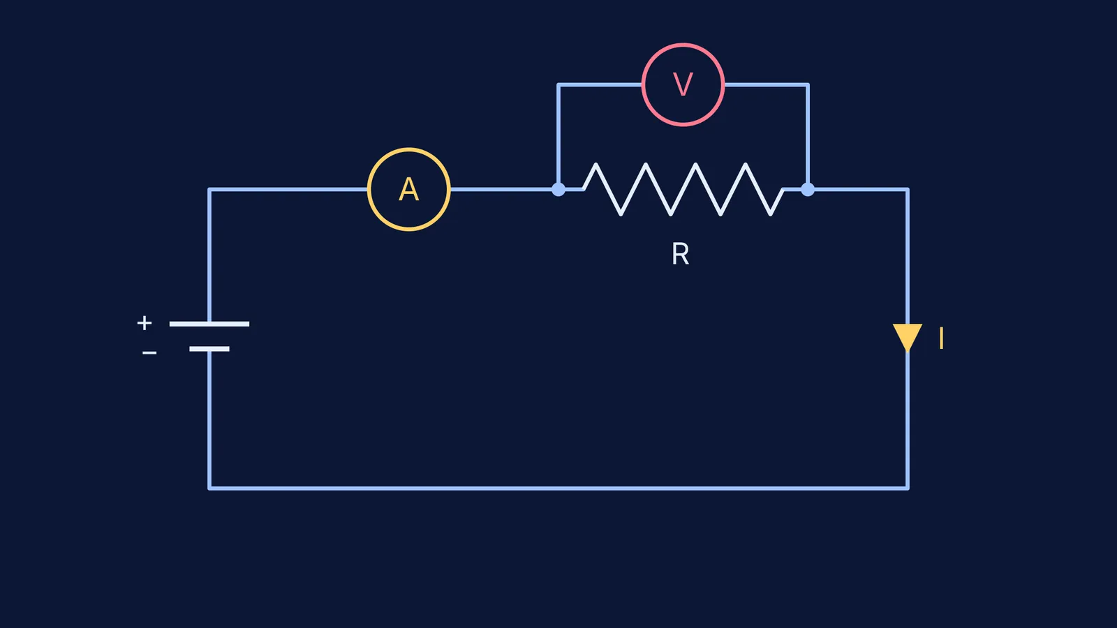
The symbols are a circle with A for an ammeter and a circle with V for a voltmeter. Drawing them right takes four steps:
Draw the main loop first: cell, key, rheostat and the resistor, with no meters.
Break the loop at one point and put the A circle in the gap. It can go anywhere in that loop, because the current is the same everywhere in a series path.
Put a dot on the wire at each end of the resistor. Draw the V circle above the resistor and join it to the two dots.
Mark + and − on both meters. The + terminal faces the cell's + side, along the conventional current.
A quick check: trace any path round the main loop with your finger. You should pass through the A circle, and you should never be forced through the V circle.
This exact set-up is the core of the resistivity of a wire experiment, where you read V and I in pairs and plot the graph.
How do you practise meter questions?
Exam questions swap two meters, give a meter a real resistance, or ask for a reading after a change. Work each one as above: redraw the circuit, replace each meter by its resistance, then solve it like any other network.
If you get the method wrong, the Fermi Problem Library has worked problems with a step-by-step solver that explains the reasoning rather than printing an answer. If circuits are easier for you to picture than to read about, the Fermi Simulation Lab has interactive simulations for ideas that are easier to see than to read.
Tonight, draw one circuit with both meters in the right places, then redraw it with them swapped and work out both wrong readings.


