
On this page
Current peaks at resonance in a series LCR circuit, yet in a parallel LC circuit the supply current falls almost to nothing at the same frequency. Both follow from one fact: inductor and capacitor quantities are 180° apart. What differs is what cancels.
What happens to current at resonance in a series LCR circuit?
In a series circuit the same current flows through R, L and C, and the voltages across L and C point in opposite directions. NCERT's Class 12 Physics chapter on alternating current (Section 7.6.2) shows that when X_C = X_L, impedance falls to its minimum, Z = R, at the resonant frequency ω₀ = 1/√(LC). At that frequency the current amplitude is at its maximum, i_m = v_m/R.
With the L and C voltages cancelled, only R limits the current. See our post on deriving LCR impedance and the resonant frequency for the full working.
Why is current minimum at resonance in a parallel LC circuit?
Now connect L and C side by side across one supply. The voltage is shared, and each branch draws its own current: V/X_L through the inductor (lagging V by 90°) and V/X_C through the capacitor (leading V by 90°), as NCERT derives. The two point in opposite directions.
At ω₀ = 1/√(LC), X_L = X_C, so the branch currents are also equal in size and add to zero at the junction. Bilkent University's lecture notes on tuned circuits show that an ideal parallel LC pair has impedance jωL/(1 − ω²LC), which becomes infinite at ω₀, and that the inductor current is exactly 180° out of phase with the capacitor current. Infinite impedance means zero line current.
That is why it is called a rejector circuit: at resonance its impedance is maximum, so it rejects current at its own frequency, as Electronics Tutorials explains.
How do you draw the phasor diagram for a parallel LC circuit?
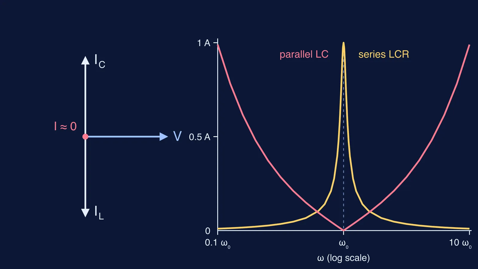
Four steps, using NCERT's 90° phase results, give the diagram at the top:
Draw V horizontally. It is the shared quantity, so it is your reference.
Draw I_C straight up (leads by 90°), length V/X_C.
Draw I_L straight down (lags by 90°), length V/X_L.
Add them head to tail. Below ω₀, I_L is longer and the net current points down (inductive). Above ω₀, I_C wins (capacitive). At ω₀ the sum shrinks to a point.
To practise, try asking AI to describe an RLC phasor diagram, then checking it.
Series vs parallel: what do the numbers look like?
Take the values NCERT uses for Figure 7.14 in the same chapter: L = 1.00 mH, C = 1.00 nF, a 100 V peak source, and R = 100 Ω for the series case. NCERT gives ω₀ = 1.00 × 10⁶ rad/s, where X_L = ωL and X_C = 1/ωC both equal 1000 Ω. Our worked peak line currents (ideal parallel pair):
At 0.5ω₀ (X_L = 500 Ω, X_C = 2000 Ω): series 0.067 A; parallel branches 0.20 A and 0.05 A, net 0.15 A.
At 0.9ω₀ (900 Ω, 1111 Ω): series 0.43 A; parallel branches 0.111 A and 0.090 A, net 0.021 A.
At ω₀ (1000 Ω, 1000 Ω): series 1.0 A; parallel branches 0.1 A and 0.1 A, net 0 A.
At 1.1ω₀ (1100 Ω, 909 Ω): series 0.46 A; parallel branches 0.091 A and 0.110 A, net 0.019 A.
At 2ω₀ (2000 Ω, 500 Ω): series 0.067 A; parallel branches 0.05 A and 0.20 A, net 0.15 A.
The series current peaks at ω₀ exactly where the parallel current dips to zero.
If the line current is zero, where does the current go?
It circulates. At ω₀ each branch in our NCERT-value example still carries 0.1 A, as charge swings between capacitor and inductor, the same energy swap you see in LC oscillations. The supply only replaces what is lost.
Real circuits lose some energy, so the line current is almost zero, not exactly zero. The Bilkent notes model this loss as a resistor R across the pair: at ω₀ the impedance becomes R, and each branch current is R√(C/L) times the input current, which equals the quality factor Q = R/(ω₀L). With R = 100 kΩ in our example, Q = 100: the line current is 100 V ÷ 100 kΩ = 1 mA, while each branch carries 0.1 A.
How should you write this in an exam answer?
Three lines cover it:
At resonance X_L = X_C, so I_L and I_C are equal in magnitude.
I_L lags V by 90° and I_C leads V by 90°, so they are 180° apart and cancel.
Net line current is nearly zero (impedance maximum), while a large current circulates between L and C.
If you get stuck on AC numericals like these, the Fermi Problem Library has a step-by-step solver that explains the reasoning rather than printing an answer. If the gap is the idea itself, the Fermi Concept Library gives each concept its own lesson.
Before reaching for a formula, ask what the elements share: shared current means a current peak at resonance, shared voltage means a dip.