
On this page
Making an AI put a phasor diagram into words is a useful test: if it has to say where every arrow points and why, its mistakes show. Then check the final phase angle yourself with one line of trigonometry, using the prompt, worked example and checklist below.
What should a phasor diagram for R, L and C look like?
The NCERT Class 12 Physics chapter on alternating current gives the rules to check the AI against. A phasor is a vector that rotates about the origin with angular speed ω, and its vertical component gives the instantaneous value of the voltage or current (section 7.3).
Resistor: the voltage and current phasors point in the same direction, so the phase angle is zero.
Inductor: the current lags the voltage by π/2, a quarter of a cycle.
Capacitor: the current leads the voltage by π/2.
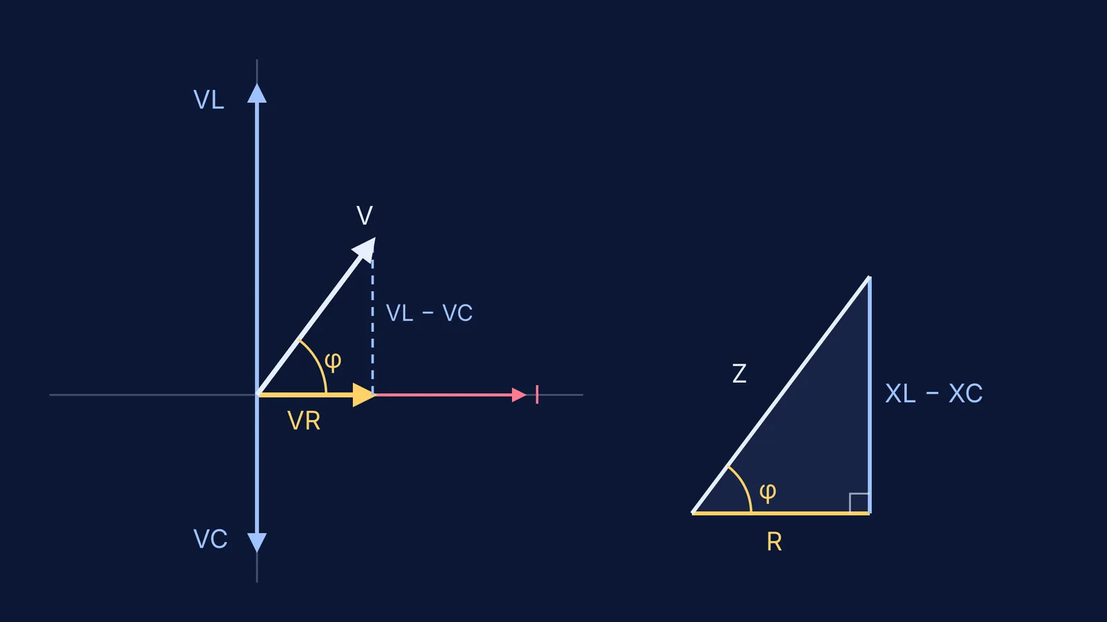
In a series LCR circuit the same current flows through every part, so NCERT builds the diagram around the current phasor: VR along it, VL π/2 ahead, VC π/2 behind. VL and VC are opposite, so they combine into one phasor of size |VC − VL|, and the source voltage V is the hypotenuse of a right triangle.
The impedance of a series LCR circuit is Z = √(R² + (XC − XL)²), and the phase angle satisfies tan φ = (XC − XL)/R (NCERT, equations 7.26 and 7.27). The reactances are XL = ωL and XC = 1/ωC.
How do you ask AI to describe an RLC phasor diagram in words?
Ask for the diagram one arrow at a time, and make the AI commit to directions before it does any arithmetic. Paste this:
"Describe a series RLC phasor diagram in words, step by step. Do not give the final answer yet."
"Start with the current phasor as the reference along the positive x-axis. Then place VR, VL and VC one at a time. For each, say which direction it points and the phase angle relative to the current."
"Explain in one sentence each why VL leads the current and why VC lags it."
"Combine VL and VC, then add VR. Describe the triangle you get and say which side is the source voltage."
"State your sign convention for φ, then give tan φ and φ in degrees for R = 30 Ω, XL = 80 Ω, XC = 40 Ω."
Step 5 matters most. If the AI says the voltage leads but gives a negative φ without naming its convention, ask it to resolve the contradiction.
How do you check the AI's phase angle with tan φ?
Do the check on paper with the same numbers and NCERT's impedance and phase-angle formulas.
Net reactance: XL − XC = 80 − 40 = 40 Ω. XL is bigger, so the circuit is mainly inductive.
Impedance: Z = √(30² + 40²) = √2500 = 50 Ω.
Phase angle: tan φ = 40/30 = 4/3, so φ = 53.1°.
Direction: the circuit is inductive, so the current lags the source voltage by 53.1°. In NCERT's convention this is written φ = −53.1°, because tan φ = (40 − 80)/30 = −4/3.
Size check: with a peak source voltage of 100 V, the peak current is 100/50 = 2 A. Then VR = 60 V, VL = 160 V and VC = 80 V. VL − VC = 80 V, and √(60² + 80²) = 100 V, which matches the source.
Notice that VL (160 V) is bigger than the source voltage (100 V). That is fine, because phasors add like arrows, not plain numbers. An AI that "corrects" this has made an error.
For the derivation behind these formulas, see how to derive LCR circuit impedance and resonance frequency.
What mistakes should you catch in an AI's answer?
Swapping lead and lag for L and C. A common memory aid: in "CIVIL", I comes before V in C, and V before I in L.
Adding VR, VL and VC as plain numbers instead of as phasors.
Using (XL − XC) in one line and (XC − XL) in the next without changing the sign of φ.
Mixing radians and degrees when taking tan⁻¹.
Forgetting that φ = 0 when XL = XC. That is resonance.
To see how the current peaks when XL = XC, try this series LCR resonance simulation. For the history, read how Charles Steinmetz used complex numbers to solve AC circuits.
Where can you practise this with a tutor that draws the diagram?
Fermi's AI tutor teaches rather than just answers: it draws the figure, runs the simulation and checks your understanding as it goes, so you can compare your description with a picture. For ideas that are easier to see than to read, such as phasors rotating at ω, the Fermi Simulation Lab has interactive simulations.
Try the five-line prompt on your next AC numerical, then check the angle yourself.