
On this page
If a question shows a sine wave going into a diode and a resistor and asks for the output, you are looking at a clipper. The method never changes: find when the diode turns on, then work out the output in each state. Below, we run a 5 V peak sine through a series clipper and a shunt clipper, first with an ideal diode, then with a 0.7 V silicon diode.
What does a diode clipper do?
A clipper removes the peak of a waveform, as the LibreTexts chapter on clipper circuits/03%3A_Diodes_and_Rectifiers/3.06%3A_Clipper_Circuits) defines it. The diode is a switch: off, it is an open circuit; on, it is a short (ideal model) or a fixed 0.7 V drop (silicon model). In its shunt example, the same LibreTexts page notes that the waveform is clipped at −0.7 V because of the silicon diode's forward voltage drop.
The two layouts differ only in where the diode sits:
Series clipper: the diode sits in the line between input and output, and you take the output across a resistor.
Shunt (parallel) clipper: a resistor sits in the line, and the diode is connected across the output terminals.
What is the output waveform of a series diode clipper?
Take vin = 5 sin ωt, with the diode's anode facing the input.
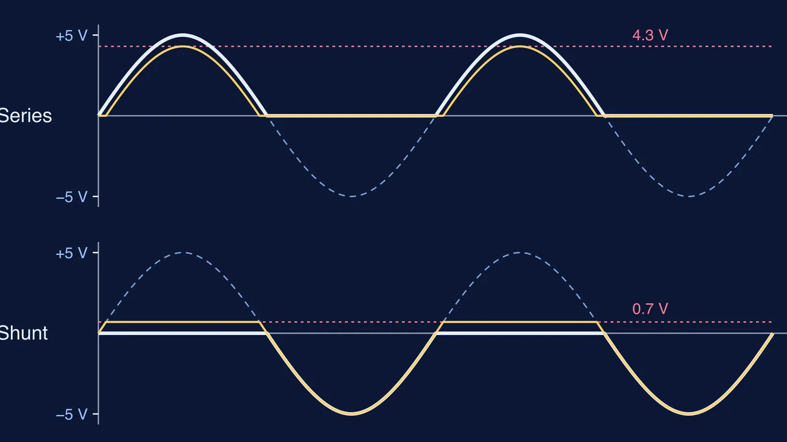
With an ideal diode, the diode conducts on the positive half-cycle and vout = vin, up to 5 V. On the negative half-cycle it is reverse biased, no current flows, and vout = 0. You get positive humps with flat gaps, the same shape as a half-wave rectifier. Our half-wave and full-wave rectifier guide works through that circuit in more detail.
With a 0.7 V diode, the diode stays off until vin reaches 0.7 V. After that, vout = vin − 0.7, so the output peak is 5 − 0.7 = 4.3 V. Each hump also starts late: sin θ = 0.7/5 = 0.14 gives θ ≈ 8°, so the diode conducts from about 8° to 172°.
If you flip the diode, everything mirrors: you get negative humps that bottom out at −4.3 V.
What is the output waveform of a shunt diode clipper?
Now put the resistor in the line, with the diode across the output. Its anode connects to the output node and its cathode to ground.
With an ideal diode, the diode conducts on the positive half-cycle and shorts the output, so vout = 0 and the input appears across the resistor. On the negative half-cycle the diode is off; with no load, no current flows through the resistor, so vout = vin, down to −5 V. The shunt clipper removes the positive half and keeps the negative one, the opposite of a series clipper with the same diode direction.
With a 0.7 V diode, the output follows the input up to 0.7 V, then the diode turns on and holds it there. The positive half becomes a flat shelf at 0.7 V; the negative half is untouched. Reverse the diode and you get the version shown in the LibreTexts clipper chapter/03%3A_Diodes_and_Rectifiers/3.06%3A_Clipper_Circuits): the negative half clipped at −0.7 V.
How do you draw a clipper output waveform step by step?
Use this routine on any clipper, including biased ones:
Find the turn-on condition: 0.7 V for a silicon diode alone, VB + 0.7 with a battery VB in series (just VB if ideal).
Write vout for the OFF and ON states.
Draw the switching level as a dashed line across the input sine.
Trace the output with the right expression on each side of that line, and label the peak and clip level.
Worked example: a shunt clipper with input 5 sin ωt and a 2 V battery in the diode branch, the diode's cathode to the battery's positive terminal and its negative terminal to ground.
Ideal diode: the output follows the input up to 2 V, then stays at 2 V. The negative half is unchanged down to −5 V.
0.7 V diode: the diode now needs the output to reach 2 + 0.7 V, so the clip level moves up to 2.7 V.
In the NPTEL lecture on clipper and clamper circuits, with a 3 V bias, including VON = 0.7 V moves the switching point from 3 V to 3.7 V.
To check an unfamiliar arrangement, the Fermi Problem Library has worked problems with a step-by-step solver that explains the reasoning rather than printing an answer.
What mistakes cost marks in clipper questions?
Drawing a full 5 V peak for a silicon series clipper. The peak is Vm − 0.7.
Mixing up series and shunt behaviour. Use the one-line test.
Leaving the clip level unlabelled.
With several diodes, assuming their states without checking. Our ideal diode circuit problems guide shows how to test each assumption.
The 0.7 V figure comes from the diode's forward-bias curve, which our guide to reading p-n junction diode characteristics explains. If barrier potential still feels shaky, the Fermi Concept Library gives each physics concept its own lesson. Try drawing all four waveforms from memory before your next practical.