
On this page
A pure inductor resists *changes* in current. On AC, that one fact puts the current a quarter cycle behind the voltage. Here is the derivation, the picture and a worked mains example.
How does V = L di/dt lead to a 90° lag?
The derivation below follows section 7.4 of the NCERT Class 12 Physics chapter on Alternating Current. Take a source v = vm sin ωt across an inductor with no resistance. Kirchhoff's loop rule gives v − L di/dt = 0, where the second term is the self-induced emf (its minus sign comes from Lenz's law).
Rearrange: di/dt = (vm/L) sin ωt. The voltage fixes the slope of the current, not the current itself.
Integrate: i = −(vm/ωL) cos ωt + constant.
The source swings evenly about zero, so the current does too. The constant is zero.
Since −cos ωt = sin(ωt − π/2), you get i = im sin(ωt − π/2), with im = vm/ωL.
In a pure inductor, the current lags the voltage by π/2, or a quarter of a cycle (NCERT; OpenStax University Physics).
The quantity ωL plays the role of resistance and is called inductive reactance, XL = ωL, measured in ohms (NCERT). It grows with frequency, which is why a coil passes slow changes easily and fights fast ones.
What do the phasor diagram and graph show?
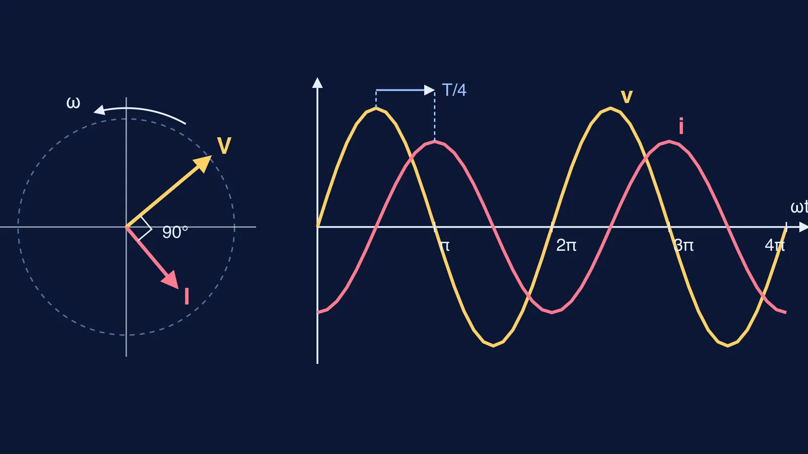
On a phasor diagram, both phasors rotate anticlockwise at ω. The current phasor I sits π/2 behind the voltage phasor V, and their projections on the vertical axis give the instantaneous values (NCERT).
On the graph against ωt, the voltage peaks at ωt = π/2 and the current peaks at ωt = π. The current reaches its maximum one-fourth of a period, T/4, after the voltage does (NCERT). A quick self-check: wherever v is at a peak, i should be crossing zero, and wherever i is at a peak, v should be zero.
In a capacitor the current *leads* by π/2; compare with our post on why a capacitor blocks DC but lets AC through.
Why is the average power in a pure inductor zero?
Multiply the two: p = iv = −(im vm/2) sin 2ωt. That swings positive and negative at twice the supply frequency, and the average of sin 2ωt over a full cycle is zero (NCERT). OpenStax puts it the same way: capacitors and inductors absorb energy from the circuit during one half-cycle and give it back during the other, so their average power is zero (OpenStax, Power in an AC Circuit).
In the general formula P = Vrms Irms cos φ, a pure inductor has φ = 90°, so cos φ = 0. Current flows, but no average power is drawn: wattless current. Our posts on RMS values and power in AC circuits and why a choke coil is used instead of a resistor take this further.
Worked example: a 0.1 H coil on 220 V, 50 Hz mains
NCERT treats the 220 V household line voltage as an rms value with a peak of √2 × 220 V = 311 V, and its Example 7.2 uses 220 V at 50 Hz (NCERT). Treat the 0.1 H coil as pure.
Angular frequency: ω = 2π × 50 = 314 rad/s.
Reactance: XL = ωL = 314 × 0.1 = 31.4 Ω.
RMS current: Irms = 220 / 31.4 = 7.0 A.
Peak current: im = √2 × 7.0 = 9.9 A.
Time lag: T = 1/50 s = 20 ms, so the current peaks T/4 = 5 ms after the voltage.
Instantaneous power: p swings between +1540 W and −1540 W (vm im/2 = 311 × 9.9 / 2), at 100 Hz.
Energy stored at peak current: ½ L im² = 0.5 × 0.1 × 9.9² ≈ 4.9 J. The coil takes this in over one quarter cycle and returns it to the supply over the next.
Average power: zero.
So 7 A flows, yet the coil uses no average power. Check your method against NCERT's Example 7.2, where a 25.0 mH coil on 220 V, 50 Hz gives XL = 7.85 Ω and 28 A (NCERT).
How to remember it in an exam
Start from v = L di/dt; everything else follows.
Inductor: current lags by 90°. Capacitor: current leads.
XL = ωL, and ω = 2πf, not f.
Pure L or pure C: cos φ = 0, zero average power.
If the slope argument still feels slippery, the Fermi Concept Library has its own lesson for each idea in physics, showing where it fits on the map. For more AC numericals, the Fermi Problem Library works each step and explains the reasoning rather than just printing the answer.