

On this page
Two plates with an insulator between them should not carry current at all. Yet amplifiers depend on capacitors that pass some signals and stop others. No charge ever crosses the gap; what changes is how often the plates fill and empty.
What happens to a capacitor in a DC circuit?
Connect an uncharged capacitor to a battery through a resistor. Electrons pile onto one plate and leave the other, so a current flows in the wires even though nothing crosses the dielectric. As charge builds up, the capacitor's voltage Q/C rises and pushes back against the battery. When that voltage equals the battery's, the push from the battery is cancelled and the current falls to zero.
That is the steady state. OpenStax College Physics puts it in one line: if the frequency goes to zero (DC), X_C tends to infinity, and the current is zero once the capacitor is charged.
So "blocks DC" means "blocks steady DC after a short charging time". For the time it takes to charge, see our guide to RC circuits, charging and the time constant. For exam problems where you find the charge and voltage once everything has settled, see capacitors in DC circuits at steady state.
Why does a capacitor allow AC to pass?
With AC the supply keeps reversing. The plates charge one way, discharge, then charge the other way, every cycle, so charge keeps moving back and forth in the wires.
The size of that current depends on how fast the voltage changes. Because Q = CV, the current is I = C dV/dt. Speed the voltage up and dV/dt grows, so more current flows for the same peak voltage. That is the whole idea behind reactance.
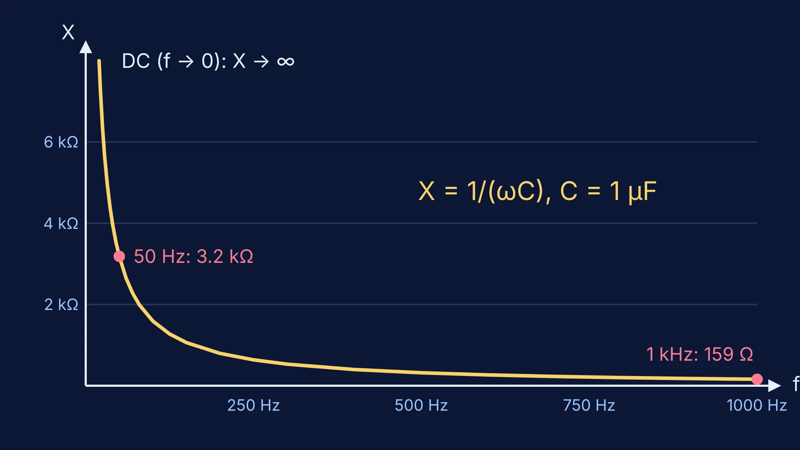
OpenStax University Physics defines capacitive reactance as X_C = 1/(ωC). Like resistance, it is a ratio of voltage to current, and it depends inversely on frequency, so high frequency means low reactance. At very high frequencies, OpenStax College Physics adds, the capacitor acts like a simple wire.
The University Physics text also says that the current through a capacitor leads the voltage across it by π/2, a quarter of a cycle.
How does reactance change with frequency? A worked example
Use X_C = 1/(2πfC), the form given in OpenStax College Physics, for a 1 µF capacitor:
f = 0 (steady DC): X_C is infinite, so no current flows.
f = 50 Hz: X_C = 1/(2π × 50 × 10⁻⁶) ≈ 3,180 Ω.
f = 1 kHz: X_C ≈ 159 Ω, twenty times smaller.
f = 100 kHz: X_C ≈ 1.6 Ω, nearly a wire.
The reactance is inversely proportional to f: multiply f by 20 and X_C drops by a factor of 20. The textbook's own Example 23.11 shows the same pattern: a 5.00 µF capacitor on 120 V rms draws 0.226 A at 60 Hz but 37.7 A at 10 kHz.
A quick check for any answer: if you double C or double f, X_C must halve. If your number went the other way, you have probably used ωC where you needed 1/(ωC).
Where are coupling and filter capacitors used?
Coupling (DC blocking). A capacitor in series between two amplifier stages passes the audio signal but stops the DC bias of one stage from upsetting the next. High-pass filters are used for AC coupling at the inputs of many audio power amplifiers, to keep DC from being amplified and harming the amplifier.
Removing hum. OpenStax notes that a capacitor in series with a sound system rids it of the 60 Hz hum.
RC high-pass filter. A series capacitor followed by a resistor to ground passes frequencies above the cutoff f_c = 1/(2πRC) and weakens those below it, as set out on the high-pass filter page.
Try the numbers. A 10 µF coupling capacitor feeding a 10 kΩ input gives f_c = 1/(2π × 10⁴ × 10⁻⁵) ≈ 1.6 Hz. DC is blocked, while speech and music, far above that, pass almost untouched.
How do you answer this in a board or JEE exam?
A three-line answer that covers the key points:
Reactance of a capacitor is X_C = 1/(ωC) = 1/(2πfC).
For DC, f = 0, so X_C is infinite; after charging, no current flows, so the capacitor blocks DC.
For AC, f is non-zero, so X_C is finite and falls as f rises; the plates charge and discharge each cycle, so AC flows.
When a question mixes a capacitor with an inductor and a resistor, move on to phasors and impedance, set out in AC circuits for JEE: phasors, impedance and resonance. If you get stuck on a circuit and want to see where your method went wrong, the Fermi Problem Library has a step-by-step solver that explains the reasoning rather than printing an answer. To revisit the idea behind reactance itself, look it up in the Fermi Concept Library.


