
On this page
The Wheatstone bridge is a short section in Class 12 current electricity, and an easy one to learn by rote and then get wrong. Two questions cause many of the mistakes: which resistor do you solve for, and which way does the needle swing when the bridge is off balance? A simulation lets you answer both by predicting first and then checking.
What is the balance condition of a Wheatstone bridge?
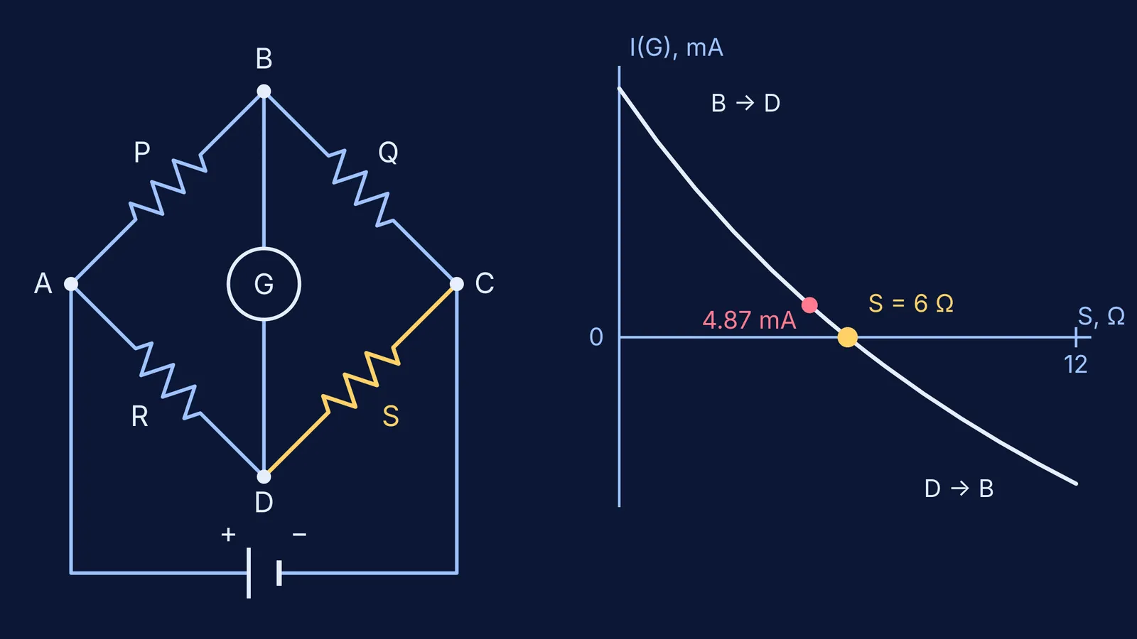
Label the circuit like this. A battery connects corner A (positive) to corner C. The top path runs A to B to C through resistors P and Q. The bottom path runs A to D to C through R and S. A galvanometer joins B and D.
The bridge is balanced when the galvanometer current is zero, and that happens when P/Q = R/S, as derived from Kirchhoff's rules in section 3.13 of the NCERT Class 12 Physics chapter on current electricity. NCERT names the arms R1 to R4, but it is the same ratio rule. If S is the unknown, then S = R × Q/P. NCERT adds that a practical device using this principle is the metre bridge.
Zero current means B and D are at the same potential. Each path is a voltage divider: taking C as zero, B sits at E × Q/(P + Q) and D sits at E × S/(R + S), where E is the battery voltage. Set the two equal and you get the same ratio rule.
Which way does the galvanometer swing when the bridge is unbalanced?
Current through the galvanometer flows from the junction at higher potential to the one at lower potential. With the labels above:
If S is smaller than R × Q/P, D sits lower than B, so current flows from B to D.
If S is larger than R × Q/P, D sits higher than B, so current flows from D to B.
The further S is from the balance value, the bigger the deflection. The needle changes direction exactly at the null.
A worked example you can run in a simulation
NCERT's Example 3.7 uses arms AB = 100 Ω, BC = 10 Ω, CD = 5 Ω and DA = 60 Ω, a 15 Ω galvanometer across BD and 10 V across AC, and finds a galvanometer current of 4.87 mA (NCERT, chapter 3). In our labels that is P = 100 Ω, Q = 10 Ω, R = 60 Ω and S = 5 Ω. Build that circuit and work through it:
Predict the null before you touch anything: S = 60 × 10/100 = 6 Ω.
Set S = 5 Ω. It is below 6 Ω, so predict current from B to D. NCERT's figure draws it that way, at 4.87 mA.
Set S = 7 Ω. Predict the needle reverses. By our calculation for the same circuit, the current is about 4.5 mA from D to B.
Step S in 0.5 Ω steps and watch the reading change sign between 5.5 Ω and 6.5 Ω.
At 6 Ω, halve the battery voltage or change the galvanometer's resistance. The null should not move.
The Fermi Simulation Lab has interactive simulations for the ideas that are easier to see than to read. For the sliding-wire part of the practical, our post on testing wire resistance against length and thickness is a useful warm-up.
Why is the null method so accurate?
A null method only asks whether the current is zero, so the meter's calibration hardly matters. Henry P. Hall's history of impedance measurement explains that, as long as all the arms are linear, the bridge's balance equation is independent of the input signal level and of the detector's sensitivity. It stays the same if you swap the source and the detector. The unknown depends only on the other resistors.
Hall's history also records that Samuel Hunter Christie described the circuit in 1833. Charles Wheatstone took it up in 1843, in his Bakerian lecture in the Philosophical Transactions of the Royal Society. Hall notes that Wheatstone gave Christie full credit but described the circuit much more clearly, and it still carries Wheatstone's name.
Where does a real bridge go wrong?
The Wheatstone bridge experiment from India's Virtual Labs lists three limits worth knowing for viva questions:
For low resistances, the resistance of the leads and contacts becomes significant.
For very high resistances, the galvanometer becomes insensitive to imbalance.
Current heats the resistors and changes their resistance, and too much current can change it permanently.
A simulation with ideal wires hides the first and third problems, so use it to build intuition, not to replace the lab. If an answer looks off, see our guide on checking an AI circuit answer with a simulator. For the meters themselves, read how to connect an ammeter and a voltmeter.
For more circuit numericals, the Fermi Problem Library has worked problems with a step-by-step solver that explains the reasoning rather than printing an answer.