
On this page
Logic gates are small enough to learn in one sitting and easy to get subtly wrong in an exam. To make them stick, build each gate in a circuit simulator, write its truth table before you touch the switches, then check yourself. Along the way you will see that one gate, NAND, can make all the others.
What do NOT, AND, OR, NAND and NOR gates do?
Each gate takes inputs that are 0 (low) or 1 (high) and gives one output. Here is each gate with its four input rows, written as A, B and then the output.
NOT (one input): 0 gives 1, 1 gives 0. It flips the signal.
AND: 00 → 0, 01 → 0, 10 → 0, 11 → 1. The output is 1 only when both inputs are 1.
OR: 00 → 0, 01 → 1, 10 → 1, 11 → 1. The output is 1 when at least one input is 1.
NAND: 00 → 1, 01 → 1, 10 → 1, 11 → 0. It is AND followed by NOT.
NOR: 00 → 1, 01 → 0, 10 → 0, 11 → 0. It is OR followed by NOT.
NAND and NOR are AND and OR with the output flipped; the small circle (bubble) on a gate symbol means "invert".
How do you build logic gates in a circuit simulator?
You need a digital logic simulator, not a physics one. CircuitVerse runs in the browser and describes itself as free and open source. Logisim-evolution is educational software for designing and simulating digital logic circuits, released under the GNU GPL v3, and it runs on Windows, macOS and Linux.
Place two input toggles and label them A and B.
Drop in one gate and wire both inputs to it.
Connect the output to a light or output probe.
On paper, write the four rows 00, 01, 10, 11 and fill in the output you expect.
Only now flip the toggles, one row at a time, and tick or cross each prediction.
Swap the gate and repeat for all five.
Why predict the truth table before switching inputs?
In Crouch, Fagen, Callan and Mazur's study in the American Journal of Physics (2004), students who passively observed classroom demonstrations understood the concepts no better than students who did not see them at all. Students who predicted the outcome before seeing the demonstration showed significantly greater understanding.
A truth table is a tiny demonstration with four outcomes. Flip switches first and the light simply hands you the answer. Commit to a prediction first and a wrong row forces you to ask why.
For physics topics that are hard to picture, the Fermi Simulation Lab has interactive simulations for the ideas that are easier to see than to read. Write down what you expect before you run one.
How do you make every gate from NAND alone?
NAND is called a universal gate because NOT, AND, OR and NOR can all be wired from NAND gates. A classic early statement of the idea is Henry Sheffer's 1913 paper in the Transactions of the American Mathematical Society, which built Boolean algebra from a single operation. Sheffer read that operation as NOR, but the same result holds for NAND. Applying Boolean algebra to switching circuits came later, in Claude Shannon's MIT thesis, A symbolic analysis of relay and switching circuits.
Build these in order, and predict each truth table before testing:
NOT from 1 NAND: join both inputs to A. If A is 1, the gate sees 1 and 1, so it outputs 0. If A is 0, it outputs 1.
AND from 2 NANDs: feed A and B into a NAND, then pass its output through your NAND-NOT.
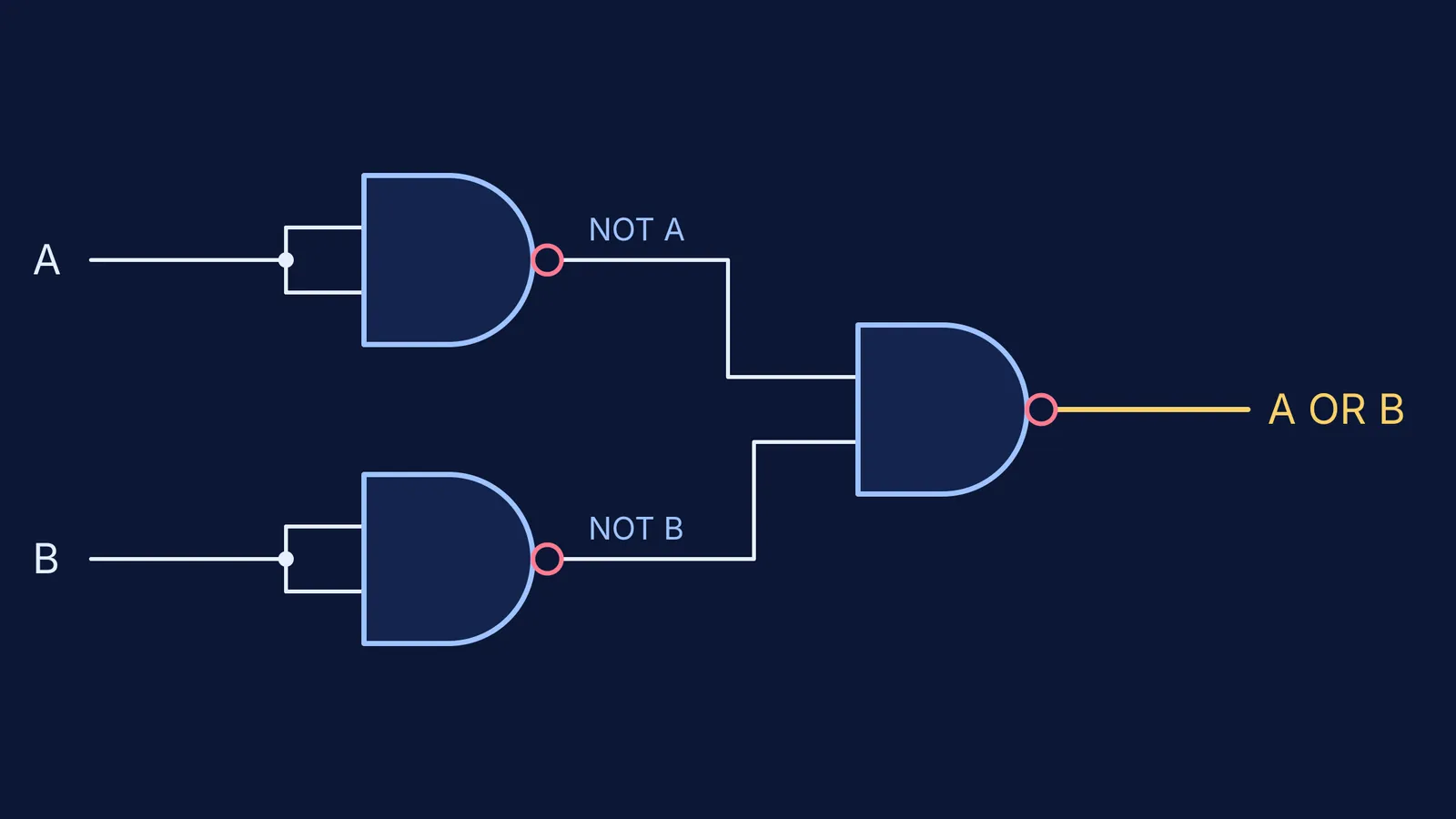
OR from 3 NANDs: make NOT A and NOT B with two NAND-NOTs, then feed both into a third NAND. This is De Morgan's law: NOT (NOT A AND NOT B) equals A OR B.
NOR from 4 NANDs: build the OR above and add one NAND-NOT after it.
Worked check for the OR build with A = 1 and B = 0: the first NAND sees 1 and 1, so NOT A is 0. The second sees 0 and 0, so NOT B is 1. The third NAND sees 0 and 1, which is not both 1, so it outputs 1. That matches OR for the row 10.
If De Morgan's law feels shaky, the Fermi Concept Library gives each concept in mathematics and computing its own lesson.
A 30-minute practice plan
Minutes 0-10: build and predict the five basic gates.
Minutes 10-20: build NOT, AND and OR from NAND only, predicting each.
Minutes 20-25: build NOR from NAND, predicting first.
Minutes 25-30: redo every crossed row in your log on paper.
Next, practise finding the output of any logic gate combination, read about Claude Shannon's thesis on Boolean logic in circuits, or see the switch under each gate in base current for a transistor switch.