On this page
In 1854, mathematician George Boole introduced an algebra based entirely on two values: true and false. For decades, Boolean algebra remained an abstract branch of mathematical logic, studied by philosophers but largely ignored by engineers.
In 1937, a 21-year-old student at the Massachusetts Institute of Technology changed that. Claude Shannon was working under the inventor Vannevar Bush on the Differential Analyzer. This machine was an early analogue computer—it solved calculus problems using a massive array of mechanical gears and shafts. However, its complex control operations were managed by a web of electromechanical telephone relays. While maintaining these relays, Shannon realised that their behaviour matched Boole's logical variables perfectly. A switch is either closed or open, meaning it carries a binary state.
Why is Claude Shannon's master's thesis so important?
Before Shannon's work, engineers designed switching circuits through intuition and trial and error. There was no systematic way to simplify a complex network of switches, nor any mathematical proof that a specific design used the fewest possible components.
In his thesis, published in 1938 as "A Symbolic Analysis of Relay and Switching Circuits" (10.1109/T-AIEE.1938.5057767), Shannon proved that arrangements of electrical relays could solve any problem expressed in Boolean algebra. By writing a physical circuit out as a mathematical equation, an engineer could use the rules of algebra to simplify the equation before building the physical machine.
This insight transformed digital circuit design from an ad hoc art into a rigorous, predictable science. The computing pioneer Herman Goldstine later called it one of the most important master's theses ever written. Because the binary properties of electrical switches are the fundamental concept underlying all digital computers, Shannon's paper is widely cited as the theoretical foundation of the information age.
How do you map logic gates to switches?
Shannon's framework showed how physical wiring corresponds directly to logical operations. If you assign a "1" to a closed circuit and a "0" to an open one, the fundamental logic gates map directly to these physical arrangements:
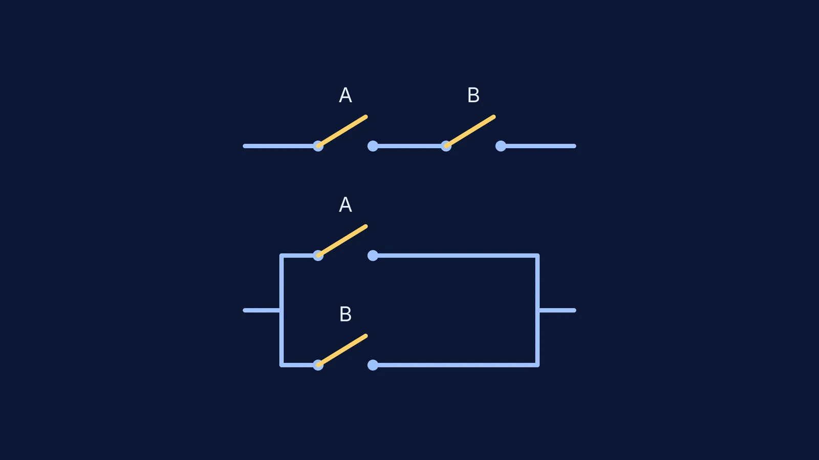
AND logic (Series): When two switches are wired in a series line, current only flows if switch A and switch B are closed. If either is open, the circuit is broken.
OR logic (Parallel): When two switches are wired in parallel branches, current flows if switch A or switch B (or both) are closed. The current simply takes the path that is available.
NOT logic (Inverter): This requires a relay that normally stays closed, but springs open to break the circuit when a control voltage is applied to its coil.
In his original paper, Shannon actually used a convention called "hindrance" where 0 meant a closed circuit (zero hindrance to the current) and 1 meant an open circuit (infinite hindrance). Today, computer scientists use the reverse, but the underlying algebra behaves exactly the same way.
How does Boolean algebra simplify circuits in practice?
To understand why this was so powerful for engineers, consider a circuit designed to turn on a warning light if a machine is too hot and spinning, or if the machine is too hot and vibrating.
If we call "too hot" switch A, "spinning" switch B, and "vibrating" switch C, the physical hardware for the statement (A AND B) OR (A AND C) requires four distinct switches: two for A, one for B, and one for C.
Using Shannon's mapping, you can write this as a Boolean equation: (A × B) + (A × C).
By applying the distributive law from algebra, you can factor out the A, simplifying the equation to A × (B + C).
This mathematically proven step translates directly back into hardware. You now place a single switch A in series with a parallel pair of B and C. You have achieved the exact same logical result using only three switches instead of four. In the 1930s, when relays were large, expensive, and drew significant power, this mathematical reduction saved physical components, copper wire, and electricity.
Shannon proved his concept by including a design for an electric adder—a circuit that could sum binary numbers automatically. It showed that circuits could not just route power, but could process information and perform mathematics.
When you are learning how these fundamental logic gates combine into complex systems, reading text is often not enough. The Fermi Simulation Lab has interactive simulations for the ideas that are easier to see than to read, allowing you to flip inputs and trace the current through a logic circuit yourself.