On this page
If you are designing a circuit to turn on an LED using a microcontroller, you cannot connect the LED directly to the control pin. The pin cannot supply enough current. Instead, you use an NPN transistor as a switch.
To make the transistor act like a closed switch, you must provide enough base current to push it out of the active region and into saturation.
What is the difference between active and saturation regions?
A transistor has three main operating states based on the base current (I_B):
Cut-off: When I_B = 0, the transistor is fully off. No collector current (I_C) flows, and the LED remains dark.
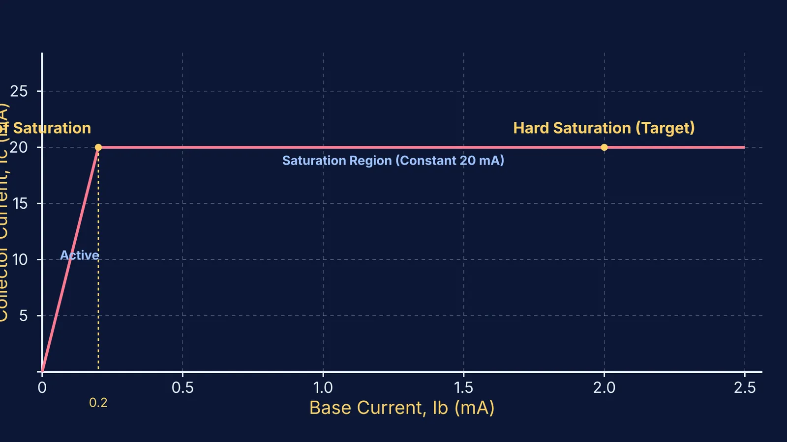
Active region: When you supply a small base current, the transistor acts as an amplifier. The collector current is proportional to the base current (I_C = β × I_B, where β is the current gain). In this state, the transistor acts like a variable resistor, dropping a significant voltage and making the LED dim. Because it drops voltage while current flows through it, the transistor dissipates power as heat. If left in this state for too long in high-power applications, the component can overheat and eventually fail. This is why a clean, rapid transition out of the active region is critical for digital switches. You can explore how semiconductor materials handle current in our guide to Energy bands: conductors, semiconductors and insulators compared.
Saturation: As you increase the base current, the collector current rises until it hits a limit set by the power supply and the LED resistor. The transistor is now "fully on." The voltage drop across it (V_CE) falls to a minimal value, and the LED lights up at full brightness.
To use a transistor as a switch, you must skip the active region and drive it firmly into saturation.
How do you calculate the base resistor for an LED circuit?
Let us calculate the exact resistors needed to light a standard red LED that requires 20 mA (0.02 A) and has a forward voltage of 2 V. We will use a 5 V power supply (V_CC), a 5 V control signal (V_in), and a standard 2N2222 transistor. For more on how LEDs behave, see our breakdown of Photodiode, LED and solar cell I-V curves for JEE Main.
First, calculate the collector resistor (R_C) that limits the LED current. In saturation, the transistor drops a small voltage, V_CE(sat), typically around 0.05–0.2 V (SparkFun). Using the upper limit of 0.2 V:
R_C = (V_CC - V_F - V_CE(sat)) / I_C R_C = (5 V - 2 V - 0.2 V) / 0.02 A = 2.8 V / 0.02 A = 140 ohms
A standard 150-ohm resistor will work perfectly.
Next, find the base current (I_B) needed to reach that 20 mA. If the transistor has a minimum gain (β) of 100, the theoretical minimum base current is:
I_B = I_C / β = 20 mA / 100 = 0.2 mA
However, β fluctuates with temperature, collector current, and from one transistor to the next—even between components from the exact same manufacturing batch. If the gain drops slightly, the calculated 0.2 mA will leave the transistor trapped in the active region, causing it to heat up while the LED stays dim. This unpredictability makes it risky to rely on the theoretical minimum base current for practical switching applications.
Using the Rule of 10, we set our target base current to 2 mA. Now we can calculate the base resistor (R_B). The base-emitter junction acts like a diode, dropping about 0.7 V (V_BE(sat)).
R_B = (V_in - V_BE(sat)) / I_B R_B = (5 V - 0.7 V) / 0.002 A = 4.3 V / 0.002 A = 2150 ohms
A standard 2.2 k-ohm resistor will put the transistor firmly into hard saturation, ensuring the LED turns fully on.
Why test circuits in a virtual simulation?
Before building a physical circuit, you should test the math. A 2023 meta-analysis published in the International Journal of Instruction found that virtual simulations improve secondary students' physics achievement with a significantly large and positive effect size of Hedges' g = 0.941 (source). The study noted that simulations help students visualise abstract phenomena and correct misconceptions through active inquiry. By observing the immediate effects of changing resistor values on the resulting currents, learners can build a much stronger intuitive grasp of circuit dynamics than by just solving equations on paper.
When you struggle to picture how electrons shift between active and saturation modes, you can use interactive simulations for learning in the Fermi Simulation Lab. A virtual environment gives you immediate feedback, letting you adjust the base resistor and watch the collector current hit its ceiling without risking a burnt-out component.