
On this page
A common emitter amplifier turns a tiny wiggle at the base of a transistor into a large, upside-down wiggle at the collector. A simulation lets you watch it happen, measure it and break it on purpose. Below is a short experiment you can run in a browser simulator, and a worked example so you know what answer to expect before you click.
What is the voltage gain of a common emitter amplifier?
Voltage gain is the output signal voltage divided by the input signal voltage, Av = vout / vin, for small signals riding on the DC bias.
With an emitter resistor RE in the circuit, the gain is Av = −gm·RC / (gm·RE + 1), which is close to −RC/RE when gm·RE is much larger than 1 (Wikipedia: Common emitter). Without an emitter resistor, the same page gives the gain as −gm·RC.
The transconductance gm equals IC/VT, where IC is the collector bias current and VT is the thermal voltage, about 25 mV at room temperature (Wikipedia: Hybrid-pi model).
Why is the output 180 degrees out of phase with the input?
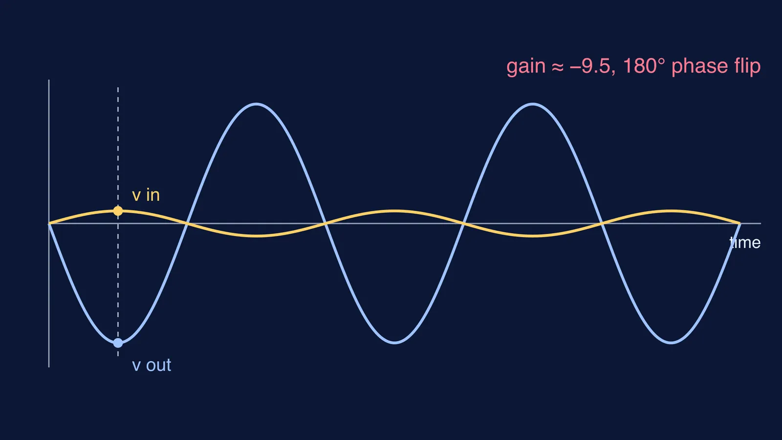
The input rises, so base current rises, so collector current rises. More current means a bigger voltage drop across RC. The collector voltage is the supply minus that drop, so it falls.
The output of a common emitter amplifier is 180 degrees out of phase with a sine wave input (Wikipedia: Common emitter). That is what the minus sign in the gain formula means: when the input peaks, the output is at its lowest point.
How do you measure the gain in a simulation?
Paul Falstad's browser-based circuit simulator includes a ready-made common-emitter amplifier example. Its notes say the circuit amplifies the input voltage about 10 times, with phase opposite to the input, because the collector resistor has 10 times the resistance of the emitter resistor; the actual gain is more like 9.5.
Run this experiment:
Open the example and let it run until the scope traces settle into steady waves.
Read the peak-to-peak input voltage and the peak-to-peak output voltage from the scope.
Divide output by input. Put a minus sign in front if the output is upside down.
Check the phase: find the moment the input peaks. The output should be at its lowest at that moment.
Change one value at a time, for example halve the collector resistor. Write your predicted gain first, then measure.
Slowly raise the input amplitude until the top or bottom of the output flattens. That is clipping, and past it the small-signal formula no longer applies.
Worked example: what gain should you expect?
James Fiore's open textbook writes the gain with the transistor's internal emitter resistance: Av = −rC / (r'e + rE), with r'e = 26 mV / IC and rC equal to RC in parallel with any load (Fiore, LibreTexts/07:_BJT_Small_Signal_Amplifiers/7.3:_Common_Emitter_Amplifier)). Take a 12 V supply, a base biased at 2.0 V, a base-emitter drop of 0.7 V, RE = 1.3 kΩ and RC = 4.7 kΩ.
The emitter sits at 1.3 V, so the emitter current is 1.3 V / 1.3 kΩ = 1.0 mA, and IC is about the same.
r'e = 26 mV / 1.0 mA = 26 Ω.
The collector sits at 12 − (1.0 mA × 4.7 kΩ) = 7.3 V, which leaves room to swing both ways.
Case 1, RE not bypassed: Av = −4700 / (26 + 1300) ≈ −3.5, close to RC/RE ≈ 3.6. A 10 mV peak input gives about 35 mV peak out, upside down.
Case 2, RE bypassed by a large capacitor: for AC the emitter is grounded, so Av ≈ −4700 / 26 ≈ −181. A 1 mV peak input gives about 0.18 V peak out. A 10 mV input is no longer small compared with VT, so expect distortion rather than a clean 1.8 V. Wikipedia notes that this high gain shifts with temperature and bias current and from one transistor to the next; an emitter resistor trades gain for stability and lower distortion.
Case 3, add a 4.7 kΩ load: rC becomes 4.7 kΩ in parallel with 4.7 kΩ, which is 2.35 kΩ, and the bypassed gain drops to about −90. Connecting a load equal to RC halved the gain.
Where else can you practise this?
IIT Kharagpur's Basic Electronics Virtual Laboratory has a CE amplifier experiment with theory, a procedure and a simulation. Its theory page explains Case 2: the emitter resistor is bypassed by a capacitor so it shorts AC while still giving DC stability.
If you want more ideas you can see rather than just read, the Fermi Simulation Lab has interactive simulations for the ideas that are easier to see than to read. When your numbers and your prediction refuse to agree, Fermi's AI tutor notices where you are stuck and decides whether to explain, ask or show.
Open the simulator, write your prediction and measure the gain.