
On this page
Say a question tells you a voltmeter reads 30 V across the resistor, 90 V across the inductor and 50 V across the capacitor of a series AC circuit. Add them up and you get 170 V. The real supply voltage is 50 V.
Why can't you just add VR, VL and VC?
In a series circuit the same current flows through all three parts, but the three voltages do not keep time with it in the same way. According to OpenStax University Physics, Volume 2, section 15.3, the resistor's voltage is in phase with the current, the capacitor's voltage lags the current by π/2 rad (90°), and the inductor's voltage leads it by π/2 rad.
So the three voltages peak at different instants. An AC voltmeter shows an rms value, as OpenStax section 15.4 explains using a household outlet as the example. Each reading tells you how big a voltage is. It does not tell you when that voltage peaks.
Adding the sizes only works for quantities that peak together. Kirchhoff's loop rule still holds at every instant: the supply voltage equals vR + vL + vC moment by moment. What fails is adding the three peak or rms readings.
What is the formula for supply voltage in a series LCR circuit?
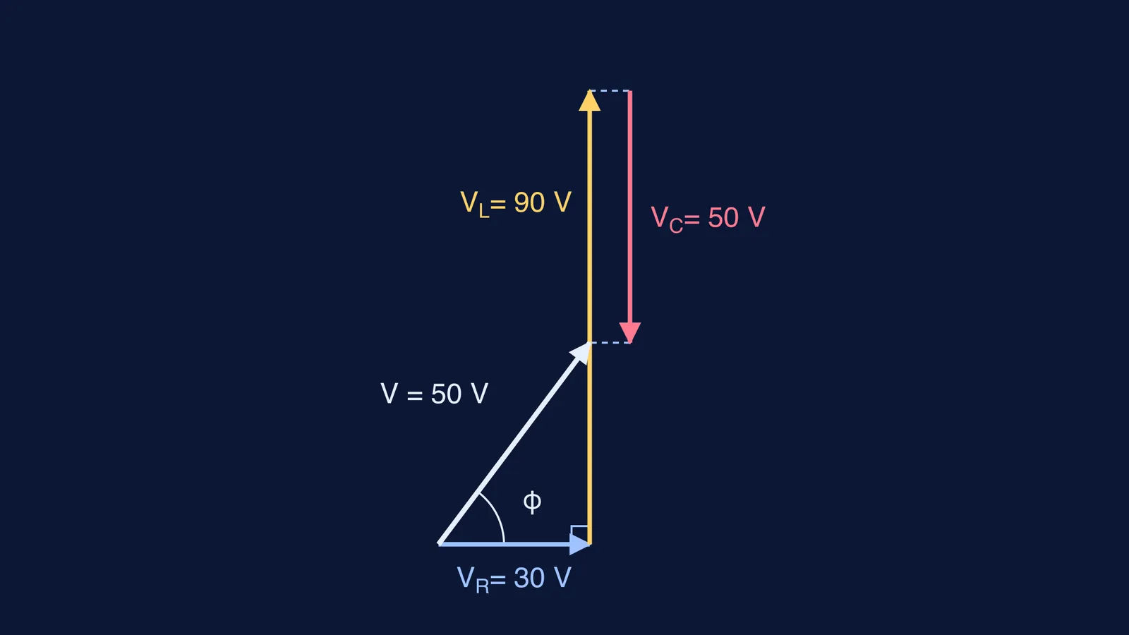
Draw each voltage as an arrow (a phasor). Take the current's direction as your reference. VR points along it, VL points 90° ahead and VC points 90° behind. That means VL and VC point in exactly opposite directions, so they partly cancel. Whatever is left over, VL − VC, sits at a right angle to VR. That gives you a right-angled triangle, and Pythagoras does the rest.
The supply voltage of a series RLC circuit is V = √(VR² + (VL − VC)²), as given in OpenStax section 15.3.
OpenStax writes this for peak values. It works just as well for meter readings, because each rms value is the peak value divided by √2 (OpenStax section 15.4), and that same factor cancels from both sides.
The same triangle gives you the phase angle between supply voltage and current: tan φ = (VL − VC)/VR. This is the OpenStax result φ = tan⁻¹((XL − XC)/R) with every term multiplied by the current. The power factor, cos φ, then equals VR/V.
Worked example: 30 V, 90 V and 50 V
Here is the OpenStax formula applied step by step.
1.Cancel the opposite pair first: VL − VC = 90 − 50 = 40 V. The inductor wins, so the circuit is inductive and the current lags the supply.
Use Pythagoras: V = √(30² + 40²) = √2500 = 50 V.
Find the phase angle: tan φ = 40/30, so φ is about 53°.
Find the power factor: cos φ = 30/50 = 0.6.
The 90 V across the inductor is bigger than the 50 V supply. That is allowed: the capacitor's voltage pulls the opposite way at every instant.
Two quick variations:
No capacitor: VR = 60 V and VL = 80 V give V = √(60² + 80²) = 100 V.
Resonance: VL = VC = 200 V and VR = 220 V give V = √(220² + 0²) = 220 V. The supply sees only the resistor, even though 200 V sits across each of L and C.
Where do students lose marks on this?
Each of these slips breaks the OpenStax phasor rule in a different way.
Adding the three readings, which gives 170 V in the example above.
Writing VL + VC inside the bracket instead of VL − VC.
Squaring all three separately: √(VR² + VL² + VC²) gives about 107 V here, which is still wrong.
Mixing peak values for one part with rms values for another. Convert everything to one kind first.
Getting the sign of φ wrong. If VC is bigger than VL, the circuit is capacitive and the current leads the voltage.
Missing a second answer in reverse questions. If you are given V, VR and VL and asked for VC, then VL − VC = ±√(V² − VR²). Both signs can give a valid VC, so check which one the question allows.
How do you practise this until it sticks?
Make one rule for yourself: sketch the phasor diagram before you write any formula. Draw VR horizontally, VL up, VC down, cancel the vertical pair, then close the triangle. It guards against most of the mistakes above.
Then do a few problems built to trap you, such as VL bigger than the supply, or VC bigger than VL. The Fermi Problem Library has worked problems with a step-by-step solver that explains the reasoning rather than printing an answer, so you can check your method one step at a time. If the 90° phase shifts still feel abstract, the Fermi Simulation Lab has interactive simulations for ideas that are easier to see than to read.
Next time three voltmeter readings appear in a question, draw the triangle first and let the arithmetic follow.