
On this page
A resistor network with an ammeter wired between two middle points is a common board and JEE question. The usual slip is not arithmetic. It is treating the ammeter as a box with some current in it instead of asking what it does to the circuit. Here is the method, a worked example and two checks.
What does an ideal ammeter do to a circuit?
An ammeter is connected in series with whatever it measures, and its resistance is normally very small compared with the other resistances, so the extra resistance is negligible, as the OpenStax College Physics chapter on DC voltmeters and ammeters puts it. An ideal ammeter takes that to the limit: zero resistance.
By V = IR, the potential difference across an ideal ammeter is zero, whatever current it carries. So the two points it joins are at the same potential, and you can treat them as one node. An ideal ammeter is a short circuit with a display on it.
Why can't you use Ohm's law on the ammeter itself?
With V = 0 and R = 0, Ohm's law gives 0/0 for the ammeter current. The reading has to come from the resistors on either side of it.
That is where Kirchhoff's junction rule comes in: the sum of currents entering a junction equals the sum leaving it. Once you know every resistor current meeting at one end of the ammeter, the leftover current goes through the ammeter. If that rule feels like something to memorise, our post on why Kirchhoff's junction rule follows from charge conservation builds it from scratch.
Three mistakes come up again and again:
Leaving the ammeter in the diagram and trying to find the voltage across it.
Merging the nodes correctly, solving the circuit, and then reporting the total current as the ammeter reading.
Assuming the ammeter reads zero because the network looks symmetric, without checking.
How do you find the reading of an ideal ammeter?
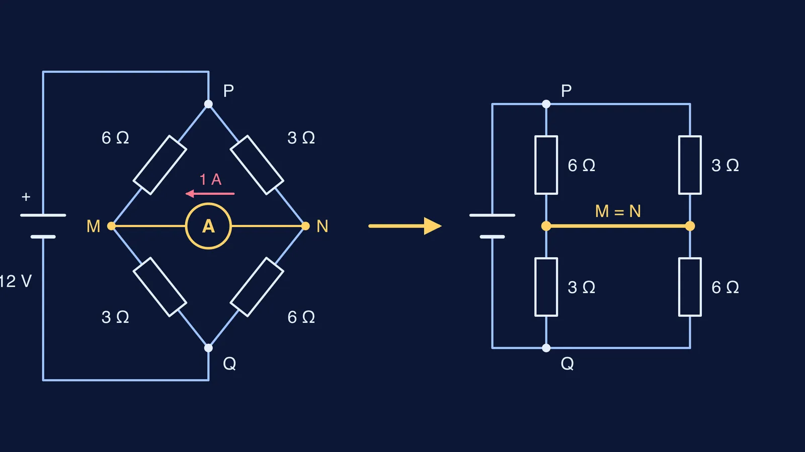
Take a 12 V ideal cell connected across points P and Q. From P, a 6 Ω resistor goes to point M and a 3 Ω resistor goes to point N. From M, a 3 Ω resistor goes to Q; from N, a 6 Ω resistor goes to Q. An ideal ammeter joins M and N. What does it read?
Redraw. Replace the ammeter with a wire and merge M and N into one node, X. The 6 Ω and 3 Ω from P now both end at X, so they are in parallel; so are the 3 Ω and 6 Ω from X to Q.
Simplify. Each parallel pair is 6 × 3 / (6 + 3) = 2 Ω. The two pairs are in series, so the total is 4 Ω.
Total current. I = 12 / 4 = 3 A.
Node potentials. Each 2 Ω block takes 3 × 2 = 6 V.
Resistor currents. P to M through 6 Ω: 1 A. P to N through 3 Ω: 2 A. M to Q through 3 Ω: 2 A. N to Q through 6 Ω: 1 A.
Junction rule at M. 1 A arrives from P but 2 A leaves towards Q. The missing 1 A must arrive through the ammeter, from N.
The ammeter reads 1 A, from N to M. Not the 3 A total: that is the second mistake above.
How do you check your answer?
Check the other end. At N, 2 A arrives from P and 1 A leaves towards Q, so 1 A leaves through the ammeter towards M. Both ends agree.
Check the direction. Take the ammeter out. Each branch is then 9 Ω, so M sits 12 × 3/9 = 4 V above Q and N sits 12 × 6/9 = 8 V above Q. N is higher, so current flows from N to M once the wire is back.
The reading is zero only when M and N are already at the same potential, which is the balanced Wheatstone bridge condition. Here 6/3 is not equal to 3/6, so a non-zero reading is expected.
What changes when the ammeter is not ideal?
A real ammeter has a small resistance, and connecting any meter adds a resistor and alters the circuit, as the OpenStax chapter notes. If a question gives the meter a resistance, treat it as a resistor in that branch and use Kirchhoff's rules as usual. For the lab side, see how to choose the right ammeter and voltmeter range.
If the method was the problem, try more networks like this in the Fermi Problem Library, where the step-by-step solver explains the reasoning rather than printing an answer. If node potentials feel shaky, the Fermi Concept Library has a lesson for each idea.
Next time you see a circled A between two middle points of a network, redraw before you calculate.