
On this page
The Wheatstone bridge is a fundamental electrical circuit used to measure an unknown resistance with high precision. According to the NCERT Class 12 Physics syllabus, the bridge is "balanced" when no current flows through its central galvanometer (Ig = 0). In this state, the ratio of the resistances in the two parallel branches is exactly equal.
Unlike a simple ohmmeter, the Wheatstone bridge uses a null deflection method. This means it measures resistance by balancing two legs of a bridge circuit so that the voltage difference between them is zero. Because no current flows through the galvanometer at the balance point, the measurement is unaffected by the internal resistance of the galvanometer or the battery.
Here is how to derive the balanced Wheatstone bridge condition using Kirchhoff's laws from first principles.
What is the circuit setup for a Wheatstone bridge?
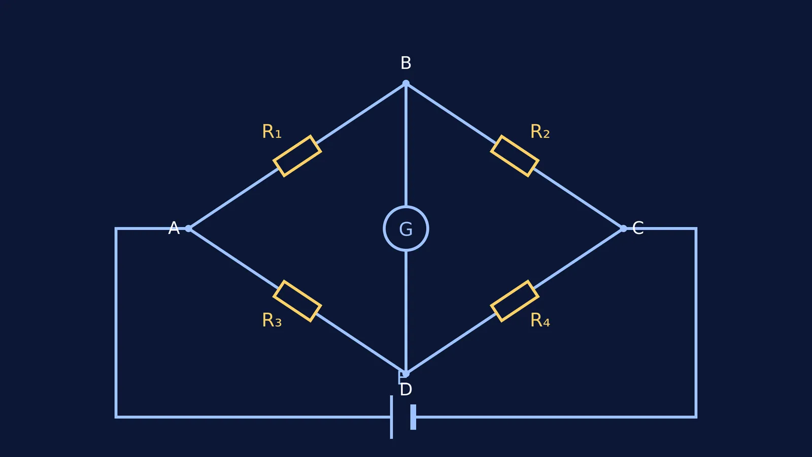
Consider four resistors R₁, R₂, R₃, and R₄ arranged in a quadrilateral loop ABCD. A battery of electromotive force E is connected across the diagonally opposite junctions A and C. A sensitive galvanometer of resistance G is connected across the other two junctions, B and D.
In this arrangement, the four resistors form the four arms of the bridge. Typically, three of these resistances are known or adjustable, and the fourth is the unknown resistance you want to measure. When the switch is closed, current flows from the battery and splits into the different branches of the network.
How do you apply Kirchhoff's junction rule?
To trace the flow of electricity, we first use Kirchhoff's junction rule (also known as Kirchhoff's Current Law). This rule states that the total current entering a junction must equal the total current leaving it, because electric charge cannot accumulate at a point.
When the total current I from the battery reaches junction A, it splits into two separate paths:
Current I₁ flows through the resistor R₁ along the branch AB.
Current I₂ flows through the resistor R₃ along the branch AD.
At junction B, the current I₁ splits again. A small current Ig goes through the galvanometer towards D, leaving a current of (I₁ − Ig) to flow through the resistor R₂ along the branch BC.
At junction D, the current I₂ coming from R₃ and the current Ig coming from the galvanometer combine. Therefore, the total current flowing through R₄ along the branch DC is (I₂ + Ig). Finally, at junction C, these currents recombine to form the original total current I returning to the battery.
How is Kirchhoff's loop rule applied to the first loop?
To find the mathematical relationship between these various currents, we apply Kirchhoff's loop rule (Kirchhoff's Voltage Law). This rule states that the algebraic sum of all potential differences around any closed circuit loop is exactly zero, which is a consequence of the conservation of energy.
We start by analysing the first closed loop, ABDA. Moving in a clockwise direction from A:
Moving from A to B through R₁ is in the direction of the current I₁, which means there is a potential drop: −I₁R₁.
Moving from B to D through the galvanometer is in the direction of Ig, meaning another potential drop: −IgG.
Moving from D back to A goes against the direction of the current I₂, which results in a potential gain: +I₂R₃.
Summing these potential changes gives the equation for the first loop:
−I₁R₁ − IgG + I₂R₃ = 0
How is Kirchhoff's loop rule applied to the second loop?
Next, we apply the exact same loop rule to the second closed loop, BCDB, again moving in a clockwise direction starting from B.
Moving from B to C through R₂ follows the direction of the current, giving a potential drop: −(I₁ − Ig)R₂.
Moving from C to D goes against the current flowing through R₄, yielding a potential gain: +(I₂ + Ig)R₄.
Moving from D to B goes against the galvanometer current, giving a potential gain: +IgG.
Summing these terms provides the equation for the second loop:
−(I₁ − Ig)R₂ + (I₂ + Ig)R₄ + IgG = 0
How do you derive the balanced condition?
The Wheatstone bridge reaches its balanced condition when the electrical potential at junction B is exactly equal to the electrical potential at junction D. Because there is no potential difference between these two points, no current can flow between them. The galvanometer shows a null deflection, meaning Ig = 0.
To find the balance condition, we substitute Ig = 0 into our two loop equations.
Substitute Ig = 0 into the first loop's equation:
−I₁R₁ − (0)G + I₂R₃ = 0
I₁R₁ = I₂R₃ (Equation 1)
Now substitute Ig = 0 into the second loop's equation:
−(I₁ − 0)R₂ + (I₂ + 0)R₄ + (0)G = 0
I₁R₂ = I₂R₄ (Equation 2)
Finally, we divide Equation 1 by Equation 2:
(I₁R₁) / (I₁R₂) = (I₂R₃) / (I₂R₄)
The current terms (I₁ and I₂) cancel out on both sides of the fraction, leaving the final balanced condition:
R₁ / R₂ = R₃ / R₄
If you know the resistance values of three of these arms, you can easily calculate the fourth. When you need to practice applying these rules to other complex circuits, the Fermi Problem Library has worked problems with a step-by-step solver that explains the reasoning rather than printing an answer.
If you want to solve physics problems step by step without relying on rote memory, deriving these circuit rules from first principles is much more reliable than trying to recall the final formula in an exam. You can also check your physics answers using dimensional analysis to ensure your derivations always make logical sense.