
On this page
The multimeter turns up in the CBSE Class 12 practical list: one Section A activity reads "To measure resistance, voltage (AC/DC), current (AC) and check continuity of a given circuit using multimeter" (CBSE Physics curriculum 2025-26). In that same document's 30-mark practical exam, one activity is worth 3 marks and the viva is worth 5.
How does a multimeter measure resistance?
An ohmmeter sends a small current through the part, measures the voltage that results and calculates resistance using Ohm's law (Wikipedia: Ohmmeter).
The basic routine, adapted from Fluke's guide to measuring resistance:
Switch off the power, disconnect the part and discharge any capacitor.
Put the black lead in COM and the red lead in the VΩ jack.
Turn the dial to Ω. With nothing connected, the display shows OL (open, or too much resistance to measure).
Hold the probes on each end of the part, fingers off the metal tips, or your body becomes a parallel path.
Read the value, then switch the meter off.
Fluke also advises taking the part out of the circuit, because components in parallel change the reading; see why a short-circuited resistor carries no current.
Which resistance range should you choose on a multimeter?
Choose the smallest range that is bigger than the value you expect. In SparkFun's worked example, a 1 kΩ resistor reads 0.97 on the 20 kΩ range (970 Ω). On the 2 kΩ range it shows one more digit after the decimal point. On the 200 Ω range it shows 1 or OL, because 1 kΩ is above the range's limit.
If the display says OL with the part connected, move up one range. If you have no idea what to expect, start high and step down.
Is 970 Ω for a "1 kΩ" resistor wrong? No. SparkFun notes that many resistors have a 5% tolerance. For a 1 kΩ resistor, that allows anything from 950 Ω to 1050 Ω. That makes a good viva answer.
What does zeroing a multimeter mean?
On an analog meter, you short the probes together and turn the zero knob until the needle reads 0 Ω. Wikipedia notes this needs doing before each measurement (Wikipedia: Ohmmeter). Digital meters have no knob, but the leads still add their own resistance. Fluke puts that at typically 0.2 Ω to 0.5 Ω, and says the REL (relative) mode subtracts it for you (Fluke).
Worked example: you touch the probes together and the meter reads 0.3 Ω. A short piece of copper wire then reads 1.1 Ω. The wire's own resistance is 1.1 − 0.3 = 0.8 Ω. For a short, thick wire, that offset is a big share of the reading; see resistivity vs resistance.
How do you test a fuse or wire for continuity?
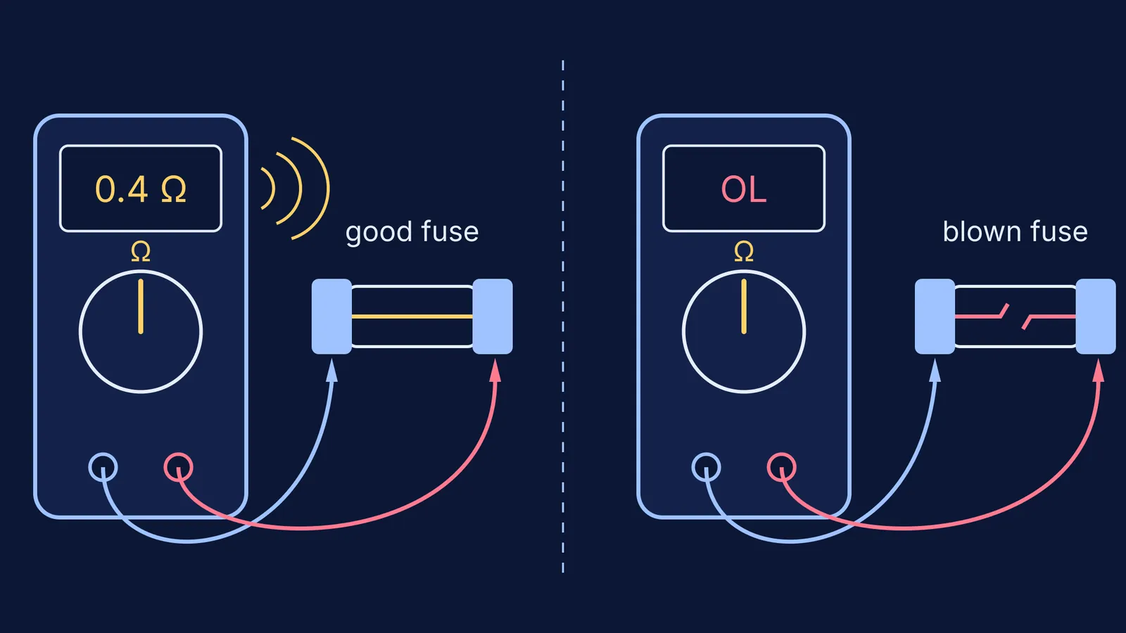
Continuity is the presence of a complete path for current to flow (Fluke's continuity guide). In continuity mode the meter beeps when that path exists. Fluke gives the example of a meter that typically beeps at 40 Ω or less on its 400.0 Ω range. Thresholds vary by meter.
Take the fuse out of its holder, or unplug the wire at both ends.
Set the dial to the continuity symbol (often shared with Ω).
Touch the probes together and check for a beep, to prove the meter works.
Put one probe on each metal end cap of the fuse, or on each end of the wire.
For a wire, bend it gently along its length. A beep that cuts in and out suggests a break inside the insulation.
How to read the result:
Steady beep and a reading close to your zero: good fuse or unbroken wire.
OL and no beep: open circuit, so the fuse has blown or the wire is broken.
A beep, but tens of ohms: suspect a poor joint or corroded contact, and measure it properly in Ω mode.
Why should you never measure resistance in a live circuit?
Wikipedia's article is direct: "An ohmmeter should not be connected to a circuit or component that is carrying a current or is connected to a power source" (Wikipedia: Ohmmeter). The meter assumes the only current in the part is its own. A battery in the circuit adds its own voltage, so the meter divides the wrong voltage by its own current and the answer means nothing. A charged capacitor does the same thing, which is why Fluke says to discharge it first.
Use a multimeter only on low-voltage lab circuits with your teacher present, and never put the probes into a wall socket; house wiring is for a licensed electrician. See also why wet hands and electricity are dangerous.
If Ohm's law or parallel paths still feel shaky, the Fermi Concept Library has a lesson for each concept and shows where it fits on the map. For circuit numericals, the Fermi Problem Library has worked problems with a step-by-step solver that explains the reasoning rather than just printing an answer.
In the lab, keep the order: power off, zero, choose the range, measure.