
On this page
This is a standard Class 12 current electricity numerical, and a common one in JEE Main practice. You get two voltmeter readings: one with the switch open, one with a resistor R connected. From just those two numbers and R you can find the cell's internal resistance. Once you know what each reading means, the method takes three lines.
What do the two voltmeter readings actually measure?
With the switch open, no current flows through the cell. OpenStax defines it plainly: the emf is the potential difference of a source when no current is flowing. So the open-circuit reading is E.
That only works because a voltmeter barely disturbs the circuit. OpenStax notes that very little current flows through the voltmeter if its resistance is a few orders of magnitude greater than the device. Textbook questions assume an ideal voltmeter unless they give you its resistance.
With the switch closed, current I flows. The terminal voltage is V = E − Ir, and it equals the emf only if no current is flowing. The voltmeter sits across the cell's terminals, which are also the ends of R, so the closed reading V is both the terminal voltage and the voltage across R.
How do you find internal resistance from open-circuit and loaded readings?
Use three steps.
Current through the load: I = V/R, because V is the voltage across R.
Voltage lost inside the cell (often called lost volts): E − V = Ir.
Divide: r = (E − V)/I = (E − V)/(V/R) = R(E − V)/V.
You can reach the same result from the circuit current, I = E/(R + r)/University_Physics_II_-_Thermodynamics_Electricity_and_Magnetism_(OpenStax)/10%3A_Direct-Current_Circuits/10.02%3A_Electromotive_Force). R and r are in series and carry the same current, so the voltages split in the ratio of the resistances: E/V = (R + r)/R. Rearranging gives the same formula.
Worked example: a 1.5 V cell and a 4 Ω resistor
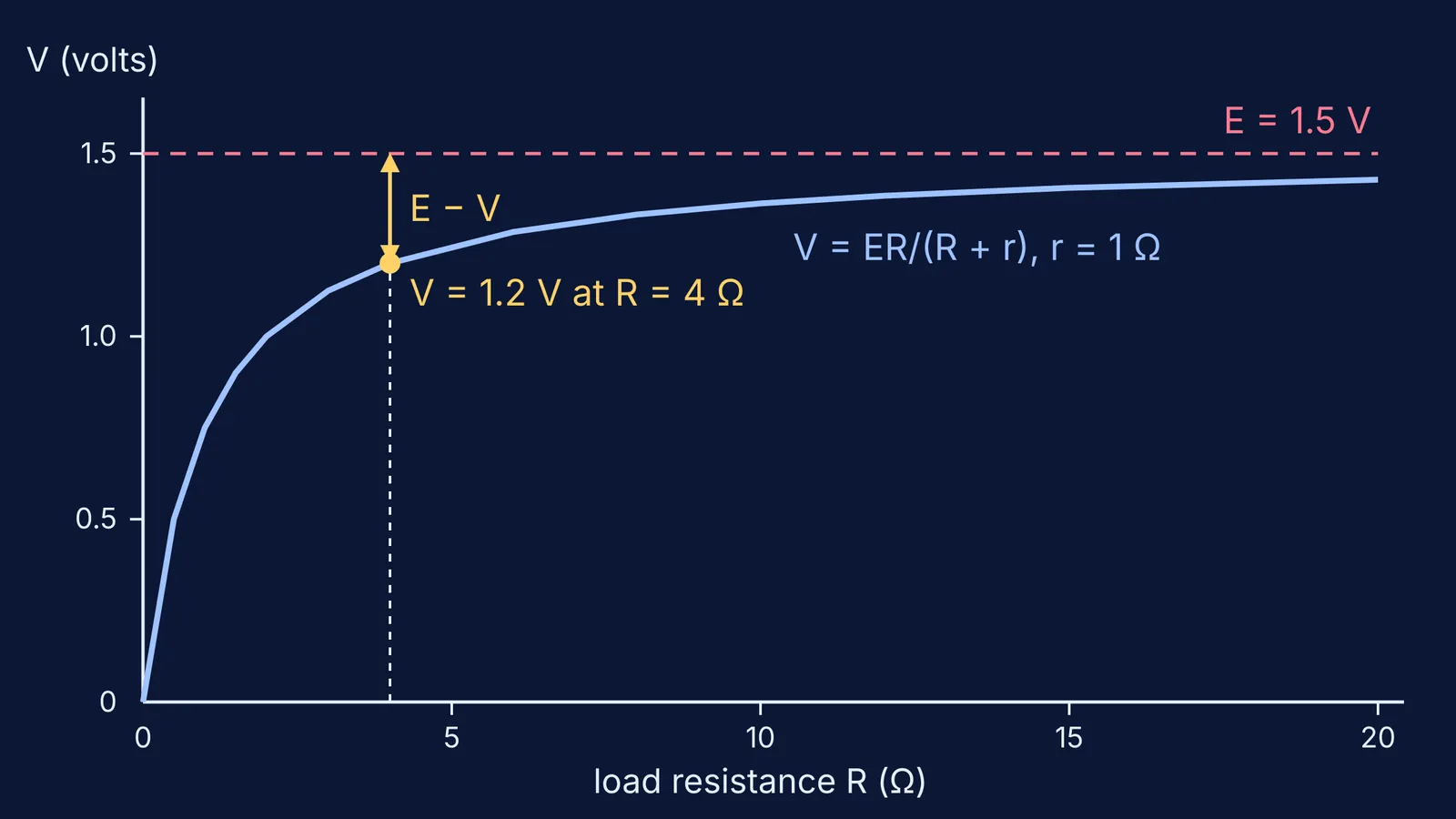
A voltmeter reads 1.5 V across a cell on open circuit. When a 4 Ω resistor is connected, it reads 1.2 V. Find r.
I = V/R = 1.2/4 = 0.3 A.
Lost volts = 1.5 − 1.2 = 0.3 V.
r = 0.3/0.3 = 1 Ω. Or in one go: r = 4 × 0.3/1.2 = 1 Ω.
Check it backwards: with r = 1 Ω, I = 1.5/(4 + 1) = 0.3 A, and V = 0.3 × 4 = 1.2 V. The answer reproduces the reading, so it is right.
A second one with less friendly numbers: E = 2.2 V, R = 5 Ω, V = 1.8 V. Then r = 5 × 0.4/1.8 = 10/9 ≈ 1.1 Ω. Check: I = 2.2/(5 + 10/9) = 0.36 A, and 0.36 × 5 = 1.8 V.
Why does the reading drop more when R is smaller?
Put I = E/(R + r) into V = IR and you get V = ER/(R + r). For the 1 Ω cell above, a 20 Ω load gives about 1.43 V, a 4 Ω load gives 1.2 V, and a 1 Ω load gives only 0.75 V. A smaller load draws more current, so more of E is lost inside the cell. The graph at the top of this post plots that curve.
This is also why a plain voltmeter is a poor battery test. OpenStax notes that battery testers use small load resistors to intentionally draw current to determine whether the terminal voltage drops below an acceptable level, and that r increases as a battery is depleted. For the same idea drawn as a straight-line graph, see finding EMF and internal resistance from a terminal voltage graph, and for the everyday version, why battery terminal voltage drops with load.
What mistakes cost marks in this numerical?
Taking the current as E/R. The current is V/R, or E/(R + r), never E/R.
Dividing by the wrong reading. The denominator is V, the loaded reading: r = R(E − V)/V, not R(E − V)/E.
Swapping the readings. For a cell that is supplying current, V is always less than E. If your r comes out negative, you have swapped them.
Mixing millivolts and volts, or kΩ and Ω, between the two readings.
Treating the voltmeter as ideal when the question gives its resistance. Then it carries current too and must be included in the circuit.
If you keep making the same slip, try a few variations in the Fermi Problem Library, where the step-by-step solver explains the reasoning rather than printing an answer. If emf and terminal voltage still feel like the same thing to you, look up emf in the Fermi Concept Library, where each concept has its own lesson and its place in the map.
Once this method feels easy, the next step is combining cells: cells, EMF and internal resistance in series, parallel and at maximum power.