
On this page
In a classroom projector, a picture the size of a postage stamp becomes one as wide as the wall. It is the same convex lens you meet in the Class 10 chapter on light, with the object placed in one particular spot.
How does a projector make a big picture on the wall?
A projector has two parts: a small, very bright picture, and a convex (converging) lens that throws an enlarged copy of it onto the wall.
In a DLP projector, the small picture is made by a chip described as "an array of highly reflective aluminum micromirrors" in DigiKey's overview of Texas Instruments' DLP technology. Each tiny mirror tilts one way for an "on" pixel and the other way for an "off" pixel. Older slide projectors used a lit photographic slide instead.
The OpenStax College Physics 2e textbook puts it in one line: a slide projector "forms an image larger than the slide, whereas a camera makes an image smaller than the object being photographed." The same section explains that a converging lens forms a real image whenever the object is farther from the lens than its focal length.
A real image is one where the light rays actually meet, so you can catch it on a wall. A University of Sydney physics activity sheet says a projector's image "must be real, because otherwise you wouldn't be able to project it onto a screen."
Where must the picture sit for the lens to enlarge it?
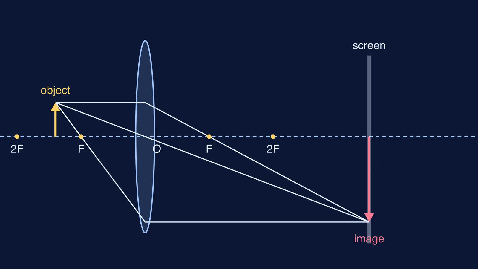
In Class 10 you learn where the image of a convex lens lands for each object position. The projector uses this case: put the object between F and 2F and you get an image beyond 2F. That image is real, inverted and larger than the object. Our guide to all six convex lens image positions for Class 10 covers every case.
You can check this with two rays from the top of the picture. One travels parallel to the axis and bends through F on the far side. The other passes straight through the optical centre. They cross far beyond 2F, below the axis.
The closer the picture sits to F, the farther away the image forms and the bigger it gets.
Worked example: how big is the picture 3 m away?
Use the Class 10 sign convention: 1/v − 1/u = 1/f and m = v/u. Suppose the projector lens has f = +2.5 cm and the wall is 3 m away, so v = +300 cm.
Find u: 1/u = 1/v − 1/f = 1/300 − 1/2.5 = 0.00333 − 0.4 = −0.39667, so u ≈ −2.521 cm.
Find m: m = v/u = 300 / (−2.521) ≈ −119.
Read the answer: the minus sign means the image is inverted, and a picture 1.2 cm wide becomes about 143 cm wide.
Now move the projector closer, so the wall is 1.5 m away. The same steps give u ≈ −2.542 cm and m ≈ −59, so the picture is about 71 cm wide. Halving the distance roughly halves the width.
Shortcut: putting the lens formula into m = v/u gives m = 1 − v/f. When v is much larger than f, the wall picture is about v/f times bigger than the one inside the projector.
Notice how little u changed: about 0.2 mm. That is why a focus ring only needs to move the lens a tiny distance.
Why is a projector's image upside down, and how is it fixed?
A real image from a single convex lens is always inverted. The University of Sydney sheet states it plainly: the image is inverted, "so the slides have to be put in upside down."
A digital projector faces the same physics. For the wall to show the picture upright, the picture on the chip has to be the other way round.
Try it at home: a phone, a magnifying glass and a dark room
Darken a room and set your phone to full brightness with a photo on the screen.
Stand about 2 m from a pale wall, phone screen facing the wall.
Hold a magnifying glass between them and slide the phone towards or away from the lens until the wall shows a sharp picture.
Notice that the picture is upside down. Rotate the phone upside down and the picture becomes upright, but any writing now reads backwards. Work out why with a ray diagram (hint: which side of the screen are you looking from?).
Never point the lens at the Sun.
For more on this, see how to tell a real image from a virtual one. If you would rather move the object and watch the rays update, the Fermi Simulation Lab has interactive simulations for ideas that are easier to see than to read. Our guide to convex lens image formation in a simulation shows what to watch as the object crosses F and 2F.