On this page
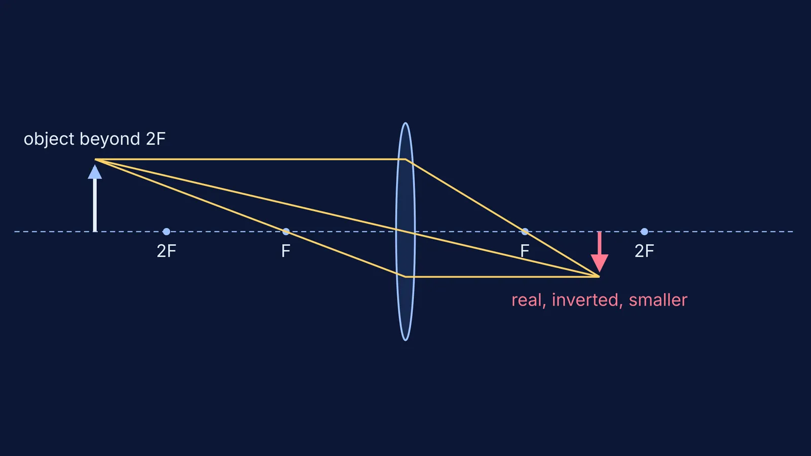
Most students learn the convex lens as a table to memorise: object beyond 2F, image between F and 2F, and so on. The table hides the most interesting moment. When the object crosses the focal point, the image jumps from one side of the lens to the other, turns the right way up, and stops being something you can catch on a screen. A simulation lets you watch that happen in a few seconds.
That matters because learning the rules is not the same as understanding them. In a 1987 study in the American Journal of Physics, Fred Goldberg and Lillian McDermott found that students who had just finished geometrical optics were often unable to relate the concepts, principles and ray diagrams they had been taught to a real object, lens and screen. Moving the object yourself, and predicting before you look, is one way to practise making that connection.
Which simulation can I use for convex lens images?
The free PhET Geometric Optics simulation from the University of Colorado Boulder lets you place an object on the principal axis and change the lens's radius of curvature, refractive index and diameter. The learning goals listed for it include refraction through converging and diverging lenses, real versus virtual images, image inversion and the focal point. It also has a ruler tool for measuring the focal point.
We built the Fermi Simulation Lab for ideas like this one, which are easier to see than to read.
What is the difference between a real and a virtual image?
A real image forms where light rays actually meet, on the far side of the lens, so you can catch it on a screen. A virtual image forms where the rays only appear to come from, on the same side as the object, so you see it by looking through the lens.
OpenStax University Physics gives the two rules this post uses: the thin-lens equation 1/do + 1/di = 1/f, and magnification m = hi/ho = −di/do. In that convention, a positive image distance means a real image on the opposite side, a negative one means a virtual image, and a negative m means the image is inverted.
If your textbook uses a different sign convention, the signs on paper will look different, but the image sizes and sides come out the same.
What happens as the object crosses the focal point?
Take a lens with f = 10 cm and move the object in, step by step. Each line below uses the two OpenStax thin-lens equations above. Before you drag the object in the simulation, say out loud where you think the image will be.
Object at 30 cm: image at 15 cm, m = −0.5. Real, inverted, half size.
Object at 20 cm (2F): image at 20 cm, m = −1. Real, inverted, same size.
Object at 15 cm: image at 30 cm, m = −2. Real, inverted, twice the size.
Object at 12 cm: image at 60 cm, m = −5. Real, inverted, five times the size, and far away.
Object at 10 cm (F): the rays leave parallel and the image forms at infinity.
Object at 8 cm: image at −40 cm, m = +5. Virtual, upright, five times the size, on the object's side.
Object at 5 cm: image at −10 cm, m = +2. Virtual, upright, twice the size.
Look at lines 4 to 6. Just outside F the image is huge, inverted and far behind the lens. Just inside F it is huge, upright and far in front. The magnification does not pass through zero; it runs off to infinity and comes back with the opposite sign. That is the moment the table hides.
The 2F position also gives the closest an object and its real image can be, which we work through in why a lens's object and real image are at least 4f apart.
How should I study this with a simulation?
Use a predict, observe, explain loop.
Predict: write down where the image will be and whether it is upright, before you move the object.
Observe: move the object and turn on the rays. Note the image distance and height with the ruler.
Explain: draw the three standard rays by hand. A ray parallel to the axis passes through F, a ray through the centre goes straight on, and a ray through F leaves parallel, as OpenStax lists them.
Check: use 1/do + 1/di = 1/f to confirm the number the simulation showed.
Repeat just outside and just inside F, where your predictions are most likely to be wrong.
Once the simulation makes sense, test it on a real bench with the u-v method for finding a convex lens's focal length, and compare the pattern with concave mirror images for all six object positions. If the numbers still feel slippery, the Fermi Problem Library has worked problems with a step-by-step solver that explains the reasoning rather than printing an answer.